Four Aspects About Multi-mode Fibers
petak , 20.05.2016.Data centers are never ceased their steps to bring greater speed and efficiency to telecommunication and datacoms industries. An enormous amount of data is transmitted, gathered and analyzed everyday, all which requires a vast number of high-bandwidth interconnections between data centers, and people. During these interconnections, fiber optic cables see their heaviest use.
Fiber optic cables can deliver more bandwidth for voice, video and data applications, and carry thousands of times more information than copper wire. With fiber optic cables, reliable and secure data transmission is ensured. Fiber optic cables are available in single-mode and multi-mode versions based on transmission mode standard. This article puts its focus on the latter version: multi-mode fiber (MMF), discussing MMF from its core size attenuation, bandwidth and manufacturing ways.
MMF: Larger Core Size
It’s known that MMF has a much larger core size and cladding diameter, whose different types are distinguished by jacket color: for 62.5/125 µm (OM1) and 50/125 µm (OM2), orange jackets are recommended, while aqua is recommended for 50/125 µm "laser optimized" OM3 and OM4. MMF’s larger core endows it greater light gathering capacity, allowing multiple modes of light to propagate through the fiber simultaneously. Thus, MMF is more suitable for relatively shorter-reach application, usually less than 600m. When it’s deployed in GbE applications, the maximum reach is 550m in combination of 1000BASE-SX SFP (ie. 1783-SFP1GSX).
MMF: Attenuation/Signal Loss
Attenuation refers to the reduction of signal loss when light travels through the fiber optic cable, which is measured in decibels per kilometer (db/km). Insertion loss is the total attenuation from all sources plus any reflection losses over a specific fiber length. Such attenuation is often caused by absorption of optical energy by tiny impurities in the fiber such as iron, copper, or cobalt. Sometimes, the scattering of the light beam as it hits microscopic imperfections, called Rayleigh scattering can also lead to signal loss phenomenon. Attenuation problem is a commonplace in MMFs.
MMF: More Bandwidth
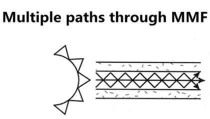
Bandwidth quantifies the complicated data-carrying capacity of MMF, given in units of megahertz-kilometer (MHz·km). Bandwidth behavior of MMF arises from multi-modal dispersion (multi-path signal spreading) which happens as the result of light traveling along different modes in the core of fibers. The bandwidth specification of performance of a MMF is verified through optical measurements during fiber manufacture. Actual system performance and data-rate handling rely heavily on bandwidth, affected by transceiver technology and device characteristics.
MMF: Manufacturing Ways
MMF can be manufactured in two ways: step-index or graded index.
Step-index fiber has an abrupt change or step between the index of refraction of the core and the index of refraction of the cladding. Multi-mode step-index fibers have lower bandwidth than other fiber designs.
Graded index fiber is designed to reduce modal dispersion inherent in step index fiber. This design maximizes bandwidth while maintaining a larger core diameter for simplified system assembly, connectivity and lower network costs. Graded index fiber is made up of multiple layers with the highest index of refraction at the core. Each succeeding layer has a gradually decreasing index of refraction as the layers move away from the center. High order modes enter the outer layers of the cladding and are reflected back towards the core. Multi-mode graded index fibers have less attenuation (loss) of the output pulse and have higher bandwidth than multi-mode step-index fibers.
MMF related transceivers: Multi-mode Transceivers
A fiber optic transceiver is a package, usually a pluggable module, comprising of a receiver on one end of the fiber and a transmitter on the other end. Over the years, multi-mode bandwidth specifications and measurement methods have evolved along with the transceiver technology, so as to keep up with delivery of higher transmission speeds. The combination of transceiver and fiber optic cable plays an important role in fiber’s practical link length. As for multi-mode transceivers which have larger core, they are often used in short-reach applications with 850mn wavelength. Listed below are several commonly-used multi-mode transceiver ports: 1000BASE-SX, 10GBASE-SR, 10GBASE-LRM, among which 10GBASE-SR port type enjoys widely deployment in 10GbE applications when the required distance is not so long. Take F5-UPG-SFP+-R for example, this F5 compatible 10GBASE-SR SFP+ transceiver listed in Fiberstore takes OM3 MMF as its transmission medium for 300m reach.

Besides what have been discussed above, there is also another MMF feature that comes into your mind: that is the affordability. MMF is less expensive than its counterpart single-mode fiber (SMF). Because of this, more people prefer MMF to SMF when the required distance is not so long. Thus, this big saving can be re-invented in other projects.
Conclusion
MMF is able to operate at data rates from 100Mbit/s to 1Gbit/s, to 10Gbit/s, to 40Gbit/s, to100Gbit/s, or even more. Choosing the right fiber type for your network project is a critical task. Here, Fiberstore MMFs provide the cost-effective combination of leading bandwidth performance and increased reliability, suitable for the demanding bandwidth interconnects. You can visit Fiberstore directly for more information about MMFs.
Oznake: MMF, Multi-mode Transceivers, 1000BASE-SX, 1783-SFP1GSX, 10GBASE SR, F5-UPG-SFP+-R
komentiraj (0) * ispiši * #
Fiber Optic Cable Basics: Construction & Certification Measurements
srijeda , 11.05.2016.Being one of the most popular and cost-effective means for communications, fiber optic cables have been installed in the backbone for years, as fiber makes communications at the speed of light possible. And their greater bandwidth and lower attenuation allow for longer distances and more channels compared with copper wires. The number of articles and papers on fiber optic cables is so large. Some are about their classifications (tight buffer/distribution/breakout/loose tube), some are on their advantage discussion (speed, distance, security), and others are meant to touch upon their related connector color codes (orange, yellow, blue). While in this article, still some basic information is included, like the construction and certification measurements.
Fiber Optic Cable Construction
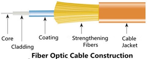
Fiber optic cable construction includes a core, cladding, coating, strengthening fibers, and a cable jacket.
Fiber Core
Fiber core refers to the light-carrying element at the center of the cable, transmitting optical data signals from an attached light source to a receiving device. The core is a single continuous strand of extruded silica glass or plastic that’s measured in microns (µm) by the size of its outer diameter. The larger the core, the more light the cable can carry. The two most common multi-mode sizes are 50 and 62.5 microns. Single-mode cores are 8.5–9 microns.
The cores of OM1 and OM2 multi-mode fiber (MMF) are made differently than the cores of laser-optimized OM3 and OM4 cable. OM1 and OM2 have a small defect in the core called an index depression. This enables them to be used with LED light sources. In contrast, OM3 and OM4 are manufactured without the center defect, which enables them to be used directly with VCSELS for greater speeds and distance. These OM3 and OM4 MMFs are widely used in Gigabit applications, especially in 10GbE transmission when they are used as the medium for 10GbE transceiver modules (ie. SFP-10G-SR).
Cladding
The optic cladding surrounds the fiber core. It functions as a boundary that contains the light waves and causes the internal refraction, enabling light to travel through the length of the fiber segment.
Coating
There is a protective acrylate coating that surrounds the core and cladding to protect them. This coating keeps the glass from dust and scratches that can affect fiber strength.
Strengthening Fibers
These components are to protect the core against crushing forces and excessive tension during cable handling, especially the installation and termination process. The materials can range from aramid yarn to wire strands to gel-filled sleeves.
Cable jacket
Fiber optic cable jacket is available in PVC and plenum-rated versions. The former type is typically used for patch connections in the data center, wiring closet, and at the desktop, while the latter kind is deployed when you need to route a cable through the buildings air plenum. Plenum cable has a flame-resistant jacket to inhibit the spread of fire.
Performance Measurements
Unlike copper cable, it’s easier to certify fiber optic cable, since it’s immune to electrical interference. When certify it, the following measurements are necessary.
Attenuation/Decibel Loss
Attenuation means the decrease of signal strength as it travels through the fiber optic cable, measured in decibels/kilometer (dB/km). Generally speaking, attenuation problems are more common to MMF.
Return Loss
This loss refers to the amount of light that is reflected from the far end of the cable back to the source. The lower the number, the better. For example, a reading of -60 decibels is better than -20 decibels. Like attenuation, return loss is usually greater with MMF.
Graded Refractive Index
This concept measures how the light is sent down the fiber, commonly mensurated at wavelengths of 850 and 1300nanometers. Compared to other operating frequencies, these two ranges yield the lowest intrinsic power loss (This is valid for MMF only.)
Propagation Delay
This is the time a signal takes to travel from one point to another over a transmission channel.
Optical Time-domain Reflectometry (OTDR)
This enables you to isolate cable faults by transmitting high-frequency pulses onto a cable and examining their reflections along the cable. With OTDR, you can also determine the length of a fiber optic cable because the OTDR value includes the distance the optic signal travels.
Notes on Fiber’s Speed & Modal Bandwidth
After introducing basic information about fiber optic cable, here, I’d like to mention two commonly-seen concepts: the first one, fiber’s speed which is not meaning the speed of the signal in the fiber, but the bandwidth potential of the fiber.
The second one, modal bandwidth which is caused by the fact that light in MMF travels in rays or "modes" that take different times to get to through the fiber, thus dispersion occurs. The longer the fiber, the greater the effect. This is the incentive driving fiber manufacturers to develop better MMFs.
Conclusion
Fiber optic cables are suitable for backbone, horizontal, and desktop applications, providing extremely reliable data transmission. They are less susceptible to temperature fluctuations, and can even be submerged in water or under sea. Fiberstore fiber optic cables come in various types with detailed specifications displayed for your convenient choice. These quality cables are designed with best-in-class performance. Besides, you can also find Push-Pull MPO cable, a kind of fiber patch cable with push-pull MPO connector here. For more information about fiber optic cables or patch cords, you can visit Fiberstore.
Oznake: fiber optic cables, MMF, 10GbE transmission, SFP-10G-SR, patch cords, Push-Pull MPO cable
komentiraj (0) * ispiši * #
10GbE Interconnect Solutions Overview
četvrtak , 31.03.2016.New sophisticated networking services, coupled with the increase of Internet users push the Internet traffic to an even higher point, driving the need for increased bandwidth consequently. One Ethernet technology—10 Gigabit Ethernet (GbE) is adequate for such bandwidth demand, and has become widely available due to the competitive price and performance, as well as its simplified cabling structure.
Several cable and interconnect solutions are available for 10GbE, the choice of which depends on the maximum interconnect distance, power budget and heat consumption, signal latency, network reliability, component adaptability to future requirements, cost. Here cost includes more than what we call the equipment interface and cable cost, but more often the labor cost. Thus, choosing a 10GbE interconnect solution requires careful evaluation of each option against the specific applications. This text aims to introduce two main 10GbE interconnect solutions: fiber optics and copper.
Fiber Optics Solution
Fiber optic cables include single-mode fiber (SMF) and multi-mode fiber (MMF). MMF is larger in diameter than that of single-mode, thus portions of the light beam follow different paths as they bounce back and forth between the walls of the fiber, leading to the possible distorted signal when reach the other end of the cable. The amount of distortion increases with the length of the cable. The light beam follows a single path through thinner single-mode cable, so the amount of distortion is much lower.

The typical 10GBASE port type that uses MMF is 10GBASE-SR which uses 850nm lasers. When used with OM3 MMF, 10GBASE-SR can support 300m-connection distances, and when with OM4 MMF, 400m link length is possible through 10GBASE-SR SFP+ transceiver.
10GBASE-LR (eg. E10GSFPLR), 10GBASE-ER and 10GBASE-ZR are all specified to work via SMF. SMF can carry signals up to 80km, so it is more often used in wide-area networks. But since SMF requires a more expensive laser light source than MMF does, SMF is replaced by MMF when the required connection distance is not so long.
Copper Solution
10GBASE-CX4, SFP+ Direct Attach (DAC) and 10GBASE-T are all specified to operate through copper medium.
10GBASE-CX4
Being the first 10GbE copper solution standardized by the IEEE as 802.3ak in 2002, 10GBase-CX4 uses four cables, each carrying 2.5gigabits of data. It is specified to work up to a distance of 15m. Although 10GBase-CX4 provides an extremely cost-effective method to connect equipment within that 15m-distance, its bulky weight and big size of the CX4 connector prohibited higher switch densities required for large scale deployment. Besides, large diameter cables are purchased in fixed lengths, causing problems in managing cable slack. What’s more, the space isn’t sufficient enough to handle these large cables.
SFP+ DAC
SFP+ Direct Attach Cable (DAC), or called 10GSFP+Cu, is a copper 10GBASE twin-axial cable, connected directly into an SFP+ housing. It comes in either an active or passive twin-axial cable assembly. This solution provides a low-cost and low energy-consuming interconnect with a flexible cabling length, typically 1 to 7m (passive versions) or up to 15m (active versions) in length. Below is the SFP+ to SFP+ passive copper cable assembly with 1m length, 487655-B21, a HP compatible 10GbE cabling product.

10GBASE-T
10GBASE-T, known as IEEE 802.3an-2006, utilizes twisted pair cables and RJ-45 connectors over distances up to 100m. Cat 6 and Cat 6a are recommended, with the former reaching the full length at 100m, and the latter at 55m. In a word, 10GBASE-T permits operations over 4-connector structured 4-pair twisted-pair copper cabling for all supported distances within 100m. Besides, 10GBASE-T cabling solution is backward-compatible with 1000BASE-T switch infrastructures, keeping costs down while offering an easy migration path from 1GbE to 10GbE.
Conclusion
In summary, two main media options are available for 10GbE interconnect: copper and fiber optics, including 10GBASE-CX4, SFP+ DAC, 10GBASE-T, 10GBASE-SR, 10GBASE-LR, 10GBASE-ER, 10GBASE-ZR, and so on. Fiberstore offers all these 10GBASE SFP+ modules and cables for your 10GbE deployment, which are quality-assured and cost-effective, like E10GSFPLR and 487655-B21 mentioned above. For more information about 10GbE interconnect solutions, you can visit Fiberstore.
Oznake: SMF, MMF, 10GBASE-LR, E10GSFPLR, SFP+ DAC, 487655-B21, 10Gbase-T
komentiraj (0) * ispiši * #
Cabling Data Center Process: Planning & Implementing its Infrastructure
utorak , 15.03.2016.Today’s data centers are the home to diverse bandwidth-demanding devices, like servers, storage systems, and backup devices which are interconnected by networking equipment. All these devices drive the need for reliable and manageable cabling infrastructure with higher performance and more flexibility for today and future growth. While managing the cabling in data centers, two main processes are included: planning the cabling infrastructure and implementing the cables.
Planning the Cabling Infrastructure
As networking equipment becomes denser, and port counts in data centers increase to several hundred ports, managing cables connected to these devices becomes a difficult challenge. Thus, during planning the cabling infrastructure, it’s wise to do the following:
Choosing Fiber Cable Assembly
This assembly has a single connector at one end of the cable and multiple duplex breakout cables at the other end, an alternative to avoid cable management. The LC (Lucent Connector) -MPO (Multifiber Push-On) breakout cable assemblies are designed to do just that. The idea is to pre-connect the high-density, high- port-count LC equipment with LC-MPO breakout cable to dedicated MPO modules within a dedicated patch panel, reducing equipment cabling clutter and improving cable management. This image below show the LC-MPO breakout cable assembly that consolidates six duplex LC ports into one MPO connection.

Nowadays, this breakout technology is widely used in 40 Gigabit Ethernet (GbE) applications. Like QSFP-4X10G-AOC10M, this product is the QSFP to four SFP+ active optical breakout cable assembly with the 10m short reach.
Using Color to Identify Cables
Color coding simplifies management and can save you hours when you need to trace cables. Cables are available in many colors (table shown below). For instance, multi-mode fiber (MMF) looks in orange (OM1, OM2) and in aqua (OM3), while yellow is usually the color of single-mode fiber (SMF) which is taken as the transmission media when the required distance is as long as 2km, or 10km . Take WSP-Q40GLR4L for example, this 40GBASE-LR4L QSFP+ transceiver works through SMF for 2km link length.

Implementing the Cabling Infrastructure
While implementing the cables, the following tasks should be obeyed by.
Testing the Links
Testing cables throughout the installation stage is imperative. Any cables that are relocated or terminated after testing should be retested. Although testing is usually carried out by an authorized cabling implementer, you should obtain a test report for each cable installed as part of the implementation task.
Building a Common Framework for the Racks
this step is to stage a layout that can be mirrored across all racks in data centers for consistency, management, and convenience. Starting with an empty 4-post rack or two, build out and establish an internal standard for placing patch panels, horizontal cable managers, vertical cable managers, and any other devices that are planned for placement into racks or a group of racks. The INTENTION is to fully cable up the common components while monitoring the cooling, power, equipment access, and growth for the main components in the racks.
A good layout discourages cabling in between racks due to lack of available data ports or power supply ports, allowing more power outlets and network ports than you need. This will save you money in the long run as rack density increases, calling for more power and network connectivity. Using correct length cables, route patch cables up or down through horizontal patch panels alleviates overlapping other ports. Some cable slack may be needed to enable easy removal of racked equipment.
Documentation
Typically, the most critical task in cable management is to document the complete infrastructure: including diagrams, cable types, patching information, and cable counts. It’s advised update the documentation and keep it accessible to data center staff on a share drive or intranet Web site.
Stocking Spare Cables
It’s suggestible to maintain an approximately the same amount on the installed cabling and ports in use, so as to face the environment variation or emergency.
Conclusion
Understanding the above-mentioned information about cabling planning and implementation helps you to have a scalable, dependable and manageable cabling infrastructure in data centers. Fiberstore offers many cable management tools, including fiber termination box, cable ties, and distribution cabinet. For more information about cable management solutions, you can visit Fiberstore.
Originally published at www.fiber-optic-components.com/cabling-data-center-process-planning-implementing-its-infrastructure.html
Oznake: cabling infrastructure, breakout cable assembly, QSFP-4X10G-AOC10M, Color coding, WSP-Q40GLR4L, SMF, MMF, cable management tools
komentiraj (1) * ispiši * #
