Introduction to 10GBASE-LR and 10GBASE-LRM SFP+
srijeda , 26.10.2016.Although the 40G/100G optical modules are on the very top trend for enterprise and data center for the interconnection, 10G transceiver modules are still in great demand. There are several types of 10G optical transceiver modules available for sale including the XENPAK, X2, XFP, small form-factor pluggable plus (SFP+) transceiver, of which 10g SFP transceiver (due to its small size and low power) is the most popular type for 10G network. According to the 10 Gigabit Ethernet standard, SFP+ transceiver can be classified into many categories: 10GBASE-SR SFP+, 10GBASE-LR SFP+, 10GBASE-ER SFP+, and 10GBASE-LRM SFP+. This article will focus on the introduction of the 10GBASE-LR SFP+ and 10GBASE-LRM SFP+ transceivers.
10GBASE-LR SFP+
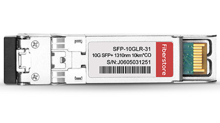
10GBase-LR can support up to 10km over single-mode fiber and uses 1310nm lasers. There is no minimum distance for LR, either, therefore it is suitable for short connections over single mode fiber too. The Cisco 10GBASE-LR module supports a link length of 10 kilometers on standard single-mode fiber (SMF, G.652). FS.COM compatible 10GBASE-LR SFP+ transceiver possesses the same function as the original one with a much lower price than Amazon and ebay. The following image shows a Cisco Compatible SFP-10G-LR SFP+.
10GBASE-LRM SFP+
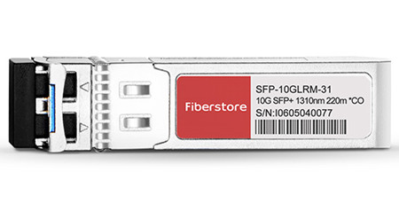
10GBASE-LRM still uses the 1310nm lasers, but it can only reach up to 220m over standard multimode fibers. The 10GBASE-LRM can be packaged in XFP and SFP+ form factors. FS.COM Cisco SFP-10G-LRM Compatible 10GBASE-LRM SFP+ supports link lengths of 220m on standard Fiber Distributed Data Interface (FDDI) grade multimode fiber (OM3/OM4). Every transceiver is individually tested on a full range of Cisco equipment and passed FS.COM’s testing with 100% compatibility. The following image shows a Cisco Compatible SFP-10G-LRM SFP+.
Besides the Cisco SFP-10G-LRM, there are a new type of the 10G SFP+ module for multimode fibers—SFP-10G-LRM2. It is a type of SFP+ transceivers compatible with the 10GBASE-LRM standard. SFP-10G-LRM2 can reach up to 2km over standard multimode fiber.
Contrast Between 10GBASE-LR and 10GBASE-LRM SFP+
At the first glimpse of the two terms—10GBase-LR and 10GBase-LRM, people usually have the misconception that they are similar with each other. In fact, 10GBase-LR and 10GBase-LRM meets different demands just as described in the above article. SFP-10G-LR optics (compatible with 10GBase-LR) supports a link length of 10km on standard single-mode fiber (SMF). SFP-10G-LRM (compatible with 10GBase-LRM) optics supports link lengths of 220m on standard Fiber Distributed Data Interface (FDDI) grade multimode fiber (MMF). When you use the OM1 or OM2 fibers connected with the 10GBase-LRM module, to make sure that specifications are met over FDDI-grade, the transmitter should be coupled through a mode conditioning patch cord. But it is fine when you use over the OM3 and OM4 fibers.
Conclusion
10G SFP+ transceiver is widely used to support communication standards including synchronous optical networking (SONET)/synchronous digital hierarchy (SDH), 10 Gigabit Ethernet and fibre channel. Both 10GBASE-LR and 10GBASE-LRM SFP+ wins its own place on the market. They cannot substitute for each other! FS.COM offers various compatible SFP+ transceivers for data centers, enterprise wiring closets, and service provider transport applications. 10G-SFP-SR, 10G-SFP-LR, 10G-SFP-LRM, 10G-SFP-LRM2, 10G-SFP-ER, 10G-SFP-ZR are all available in FS.COM. All of our SFP+ transceivers are tested and fully compatible with major brands like Cisco, HP, Juniper, Brocade and Finisar. For more information about 10G SFP+ modules, please visit fs.com.
Oznake: 10GBase-LR SFP+, 10GBASE-LRM SFP+, XENPAK, X2, XFP, SFP, 10G-SFP-SR
komentiraj (0) * ispiši * #
The Benefit and Challenge of Patch Panel
srijeda , 19.10.2016.Patch panel is undoubtedly an essential component in cabling systems as it provide a simple, neat and easy-to-manage solution. For example, if you want to wire a network system that includes multiple wall ports, patch panels will not only allow you to terminate cable elements, but the signal to be connected to the final destination. No matter how big or small your business infrastructure is, patch panel is indispensable. So what is a patch panel? What are the exact benefits of using fiber optic patch panel? This article will provide some detailed information about the benefits and challenges of them.
What Is A Patch Panel?
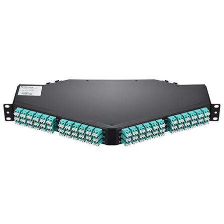
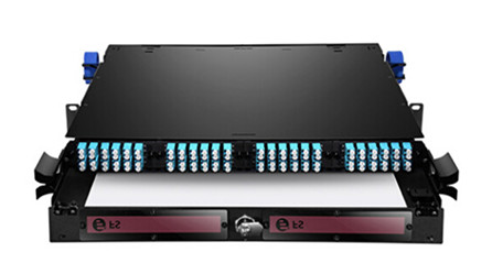
A patch panel is, in fact, an array of ports on one panel used to connect and manage incoming and outgoing LAN cables. The following image shows a 128 fibers MTP to LC/UPC OM4 1U 40GB QSFP+ Breakout Patch Panel. Each ports of patch panels connect fiber jumper cables to another port located elsewhere in your building. Circuits in an enterprise network can be easily rearranged by plugging and unplugging respective patch cords. Furthermore, patch panel provides a single location for all input jacks, which greatly simplifies the troubleshooting problems.
Patch panels are usually attached to network racks, either above or below network switches and take up 1U or 1.75 inches of space. Patch cords connect the ports in the patch panel to ports in the network switch, which creates permanent port connections to the switch that won't be interrupted during moves, adds and changes (MACs). Based on different standards, there are different types of patch panels. For instance, 48-port, 24-port and 12-port patch panels divided by the number of ports, or the more specific patch panels—Cat 5E, Cat 6, Cat 6A and Cat 7 cables. Since you have a basic understanding of patch panels, let’s move on the the next part.
The Benefit
A patch panel performs no other function except for acting as a connector, but it does offer a range of benefits:
- Use Standard Fiber Optic Cords
Since patch panel uses fiber optic cable to create interconnection, network designers can make changes and repairs without the delays and added expense associated with custom cabling.
- Flexibility and Scalability
The network can grow and change on-demand, without the costly, labor-intensive hassle of replacing channels end-to-end.
- Reduce Cable Congestion
Reduced cable slack means less clutter, less confusion and an easily organized, better-labeled cabling infrastructure. You can also manage cables in any direction–horizontal or vertical, front or back.
- Space Saving
By managing varying port densities and speeds in a single high-density patch panel, you save valuable rack space, helping to lower data center costs. A single patch panel can manage as many as (168) 10 Gb ports.
- Cost-Effectiveness
High-density and easy maintenance provide a low initial investment cost. With a patch panel, you can only buy the devices you need now, while leaving room for future expansion.
- Ease of maintenance
The advantage of using a patch panel is that it allows manual monitoring, testing, switching, routing, and other maintenance to be handled quickly because the cables in the front that connect to the more permanent cables in the back are configured and made so that changes can be made quickly and easily when needed.
The Challenge
With several patch panels available for sale, network users usually feel puzzled to select a patch panel solution with the features and capacity to meet their current needs, as well as the flexibility and scalability to adapt to and grow with the future needs. As noted before, patch panels can be divided into several types. According to different cable type, there are copper and fiber patch panels, which will be introduced in the next part.
Copper or Fiber Patch Panel?
A Patch panel can be connected with either fiber or copper cabling. The primary role of fiber patch panel is to direct signal at a required speed. It is the common sense that fiber is much faster than copper, and fiber patch panels are more expensive.
Structurally, copper panels have the 110-insulation displacement connector style on one side and 8-pin modular ports on the other. Wires coming into the panel are therefore terminated to the insulation displacement connector. On the opposite side, the 8-pin modular connector plugs into the port which corresponds to the terminated wires. With the copper panel, each pair of wires has an independent port. The following image shows the 48 Ports Shielded(STP) Cat6 Feed-Through 2U Gigabit Ethernet Patch Panel.

Fiber panels require two ports for a pair of wires. One port serves the transmitting end while the other handles the receiving end. While fiber panels tend to be faster than copper, this does not downplay the role played by the latter. And if there are more than one type of the fiber optic connector used in the network, patch panels with hybrid adapters are necessary. These adapters can then be used to plug individual fibers into other devices. The adapters on a fiber optical patch panel can come in a variety of different shapes.
Conclusion
To sum up, the patch panels make it easy to organize the fibers in an business or home network. What’s more, working with the fibers within the tray of the fiber optical patch panel protects the fibers from anything in the environment that could damage them. You can choose all range of fiber optical patch panel from FS.COM with high quality and competitive price. If you have interest, feel free to contact us.
Oznake: Patch Panel, fiber jumper cable, fiber optic cable
komentiraj (0) * ispiši * #
Migrate to 40G Ethernet With SMF&MMF 40G QSFP+ Transceiver
petak , 14.10.2016.Due to the server consolidation, virtualization, and performance improvements, data center designers are eager to migrate from 10G to 40G to better meet their network demand. However, there are many 40G optical transceivers and cabling solutions available for sale, such as QSFP-40G-SR4, QSFP-40G-LR4, QFX-QSFP-40G-ESR4, as well as QSFP DAC/AOC cables. So, which one is the most cost-effective solution? No one can give you an exact answer without the detailed information. The above 40G optical transceivers and cables have already been introduced in the previous articles. Today, I am about to shed light on a new QSFP optical transceiver—SMF&MMF 40G QSFP+ (QSFP-40G-UNIV) and its function in 40G migration.
What Is SMF&MMF 40G QSFP+ Transceiver?
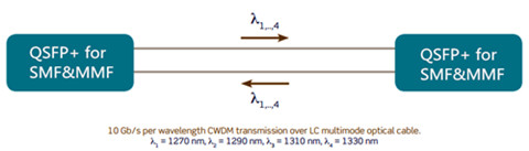
The typical fiber optic transceiver may either operate on multimode fiber or single-mode fiber. For example, the Cisco QSFP-40G-SR4, QSFP-40G-LR4 can only operate over multimode fiber for up to 150m, and single-mode fibers with a link length of 10km, respectively. However, a SMF&MMF 40G QSFP+ transceiver as the name implies, can be used with both multimode and single-mode fibers without the need for any software/hardware changes to the transceiver module or any additional hardware in the network. This is usually accomplished (seen in Figure 1) by combining four 10G optical channels at different wavelengths (1270, 1290, 1310, and 1330 nm) inside the transceiver module to transmit and receive an aggregate 40G signal over a single pair of multimode or single-mode fibers.
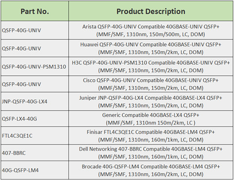
40GBASE-UNIV and 40GBASE-LX4 QSFP+ Transceiver Overview
Vendors like Huawei, Arista, H3C and Cisco all offer QSFP-40G-UNIV optical transceivers. Based on IEEE 40GBASE-LR4 specifications, QSFP-40G-UNIV operates in the 1310nm band. It uses a duplex LC connector and supports distances up to 150 m over OM3 or OM4 multimode fiber and up to 500 m over single-mode fiber (different vendor may have different specifications). Besides the QSFP-40G-UNIV transceivers, 40GBASE-LX4 QSFP+ transceiver is the other type of the SMF&MMF 40G QSFP+. Take Juniper JNP-QSFP-40G-LX4 as an example, the Juniper 40 Gbps LM4 QSFP+ optical transceiver, part of the Juniper family of optical transceivers, is optimized to fully leverage 40 Gigabit Ethernet (GbE) switches and routers. Figure 2 shows FS.COM SMF&MMF 40G QSFP+ transceiver solutions.
Why Should We Use SMF&MMF 40G QSFP+ Transceiver to Achieve 40G Migration?
With the increase in data center bandwidth requirements, migration to 40G for switch to switch connections is in higher demand. SMF&MMF 40G QSFP+ transceiver is designed to allow for seamless migrations from existing 10G to 40GbE networking without requiring a redesign or expansion of the fiber network. Besides, this transceiver also provides a cost-effective solution to migrate from multimode to single-mode fiber, allows a single-mode fiber infrastructure for distances up to 500m. The following part presents the unique merits of SMF&MMF 40G QSFP+ transceiver.
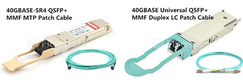
- Upgrade to 40G Without Additional Cables
The existing QSFP+ transceiver like QSFP+ SR4, QSFP+ CSR4 and QSFP+ LR4 optics, utilizes four independent 10G transmitters and receivers for an aggregate of 8 cables for 40G links. Therefore, customers have to add additional fiber to increase the number of 40G links. However, a SMF&MMF QSFP+ uses duplex LC connector that is consistent with the existing 10G connections, which are also commonly MMF cables with duplex LC connectors. Therefore, a SMF&MMF QSFP+ allows the same cables to be used for direct 10G connections to direct 40G connections, resulting in zero-cost cabling migration. What’s more, by deploying the SMF&MMF 40G QSFP+ transceiver, customers increase the number of 40G links by 4 times without making any changes to their fiber infrastructure, which greatly expand network scale and performance. Figure 3 shows the difference between QSFP+ SR4 QSFP+ and 40GBASE-UNIV universal modules.
- Realize the Migration From Multimode to Single-mode Fiber
There is a increasing trend for data center designers to move to single-mode optical solutions due to the distance limitations of the multimode cabling system. When data rates increase from 40G to 100G and beyond to 400G, it is just not that easy to move to single-mode cable system for cost effectiveness. Because network managers needs to replace all the old multimode optical devices into brand new single-mode equipment, which usually costs a large mount of money. However, with SMF&MMF QSFP+ optic module, migrating to 40G and 100G will be simpler. As SMF&MMF QSFP+ interoperates with 10km QSFP-LR4 optics, it s a cost effective solution for SM fiber infrastructure for distances up to 500 m.
- Simplify the 40G Cabling System
The SMF&MMF 40G QSFP+ transceiver offers the unique advantage of operating on both multimode and single-mode fiber without any requirement for additional hardware or software. Customers can consolidate their optics and use SMF&MMF QSFP + in their network irrespective of the fiber type, which makes full use of the existing cabling systems, reduces the cost of deployment and of support, and simplify purchasing and deployments.
Conclusion
SMF&MMF 40G QSFP+ transceiver offers a cost-effective transition path for migrations to single-mode fiber in data centers with a single transceiver that bridges the gap between multimode and single-mode optics, enabling data centers running at 10G today to seamlessly upgrade to 40G without having to re-design or modify the cable infrastructure. FS.COM offers a full range of 40G optical transceivers and cables that ensure the smooth migration to 40G data center deployments. Products like QSFP-40G-SR4, QSFP-40G-LR4, QFX-QSFP-40G-ESR4, as well as QSFP DAC/AOC cables are well-tested and fully compatible with major brand. The SMF&MMF 40G QSFP+ transceivers are also offered with very competitive price but high quality. Contact us if you are interested.
Oznake: SMF&MMF 40G QSFP+ transceiver, QSFP-40G-SR4, QSFP-40G-LR4, QFX-QSFP-40G-ESR4, QSFP-40G-UNIV, 40GBASE-LX4 QSFP+, QSFP+
komentiraj (0) * ispiši * #
Cost Comparison: Fusion Splicing Versus Pre-terminated System
srijeda , 12.10.2016.Fiber optic joints or termination is a necessary process when installing a network. Every network operators who aim to deploy a next-generation fiber network have to determine how to build a flexible, reliable and long-lasting infrastructure at the lowest possible cost. In general, there are mainly two fiber optic termination methods: splices which create a permanent joint between the two fibers, or connectors that mate two fibers to create a temporary joint. When people decide to use either method, many factors should be taken into account. Today’s article will evaluate both methods from the aspect of cost to help you choose the effective termination method.
Weighting the Two Methods
Besides the features of low loss, minimal reflectance and high mechanical strength, fiber optic termination must be compatible to the environment in which they are installed. Before we come to the cost comparison of these two termination methods, let’s firstly have a brief overview.
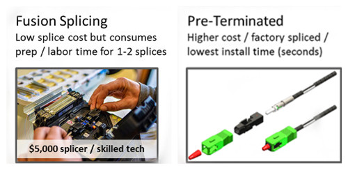
Fusion splicing
As it known to all that, splices create a permanent joint between two fibers, so its use is limited to place where cables are not expected to be available for servicing in the future. The most common application for splicing is joining cables in long outside plant cable runs where the length of the run requires more than one cable. There are two types of splices, fusion and mechanical. Fusion splicing is most widely used as it provides for the lowest loss and least reflectance, as well as providing the strongest and most reliable joint.
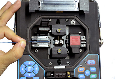
Fusion splicing machines are usually called fusion splicer available on the market that splice a single fiber or a ribbon of 12 fibers at one time. The above picture shows how to splice a fiber optic jumper. Virtually all single-mode splices are fusion. Fusion splices are made by "welding" the two fibers together usually by an electric arc. To be safe, you should not do that in an enclosed space like a manhole or an explosive atmosphere, and the equipment is too bulky for most aerial applications, so fusion splicing is usually done above ground in a truck or trailer set up for the purpose.
Today's single-mode fusion splicers are automated and you have a hard time making a bad splice as long as you cleave the fiber properly. Fusion splicers cost thousands US dollars (up to $5,000), but the splices only cost a few dollars each. The following part display the main features of the fusion splicing:
- Typical average optical losses of 0.05dB or lower
- Not de-mateable
- Special installation skills needed
- Tools sensitive to the environment
- Relatively long installation time
- Standard organizer techniques required
Pre-terminated System
Pre-termination is the alternative termination method popular on the market. Cables and fibers are terminated to a connector in the factory. When carefully planned, splicing jobs for specialized technicians can be limited to the network construction phase. But provisioning, churn and network testing can be performed by technicians without specific fiber skills, because the organizers can be very simple.
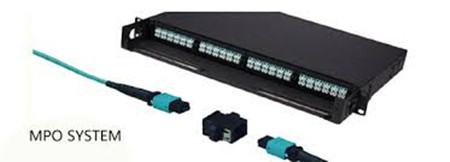
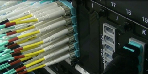
With pre-connectorized products, the connection time is reduced from 20 to less than 5 minutes, including the connector cleaning step. When connecting fibers with connector technology, there is no issue of environmental sensitivity. What’s more, connectors are accessible on the outside of the network element, reducing the need to access a product and the risk of disturbing other lines. The image below shows the MPO pre-terminated cables.
Factory pre-termination is also compatible with optical budget requirements by selecting the appropriate grade as defined by the international IEC standards. When properly planned, pre-connectorized
products do not add extra connectivity points, thus eliminating extra optical loss or reflections. In all, the most obvious features of the pre-terminated system lies in the following part:
- Typical losses of 0.15dB or less
- Fully de-mateable
- No special installation skills required
- Reduced installation time
- Very simple organizer systems
- Insensitive to environmental conditions
Cost Comparison
The start-up costs for the fusion splice are significantly higher, as fusion splicers can be very expensive. Even the cheapest fusion splicer will cost nearly $2,900 (FS-F600 Fusion Splicer from FS.COM) more than the most expensive crimp kit. Not counting the initial start-up costs, splices will run anywhere from $7.20 to $8.25 per splice, which is much lower than the pre-terminated connector. The following image shows the vivid comparison between fusion splicing and pre-terminated system.
As for the pre-terminated connector, the most significant advantage is the wire management hardware involved. A pre-terminated connector requires no additional hardware over a standard connector. And it is faster to terminate a crimp connector, saving labor time ($0.75 per splice), and splicing also requires additional material costs in the form of splice protectors ($0.40 per splice). Fiber splicing technicians have specialized training that makes them expensive when compared to someone simply plugging things in. The additional material and closet space for managing splices can cost an additional $6.05-7.10 per connector. But with a little careful planning as to lengths of fibers needed, pre-terminated fibers can be installed quickly and with no training.
In all, fusion splicing makes a lot of sense for trunk fibers and locations where there are anywhere from 48 to 192 fibers to splice. In the drop locations, where there may be only one or two splices at each location, the setup time for each location may negate any cost savings from fusion splicing.
Making the Choice
In comparing pre-termination and fusion splicing, both have their inhered advantages. Fusion splicers offer many advantages in the premises environment, from being lightweight and compact to operating on a battery. These new units minimize setup time and are ideal for use in locations where space is tight. In addition, the total splice and heater cycle time is less than one minute, thereby enabling technicians to move through many termination locations quickly.
However, we cannot deny the fact that the start up cost of the fusion splicing is huge, thus customers that can’t deal with budget are going to demand pre-terminated connectors. Pre-terminated solutions offer the most benefits: It’s easy to install pret-terminated cables, and because they’re available in custom lengths, it’s easy to get the exact lengths required to limit the excess slack. Many more users will rely on the pre-terminated trunk cables and sacrifice the inconvenience of dealing with slack, because it offers faster deployment.
As you get into significantly higher fiber counts, fusion splicing could save time over installing connectors. While for those who don’t have a fusion splicer or splicing experience, may want to consider pre-terminated connectors. FS.COM offers both fusion splicer and per-terminated cables, our products are integrated, holistic physical infrastructure solutions that guarantee a reliable and stable performance for your network. Please contact us if you need help.
Oznake: Fusion Splicing, Pre-terminated, wire management, fiber optic jumper
komentiraj (0) * ispiši * #
How to Create More Capacity in Data Center
petak , 07.10.2016.With the ever-increasing demand for more computing power and data center servers, data center manager have the responsibility to chart a data center capacity plan and determine what strategy will accommodate business needs best. Of course, they could just expand to large facilities (upgrading to the advanced switch and fiber enclosures). However, not all IT budgets are increasing, and many users just cannot afford the extra money. Therefore, people are turning to high-density and cost-effective infrastructures. To support these applications, this article will introduce a broad selection of high-density connectivity and high capacity cable management devices.
- High-Density Patch Panels
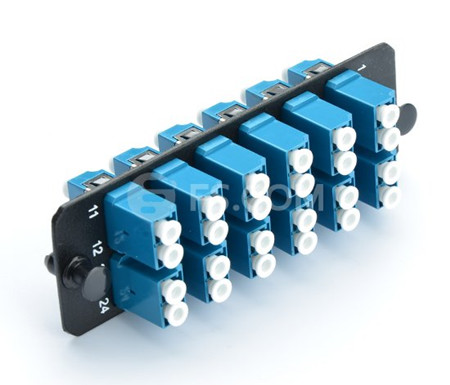
High-Density (HD) fiber patch panel solution is the most convenient approach for solving the problem of limited capacity in a data center environment. And it provides a flexible way to connect devices of different generations of equipment quickly and easily. HD patch panels consist of a panel enclosure and modular HD cassettes, which can connect a fiber network feed (via multi-strand or MTP cable) and segment it into standard LC connections in order to interface with 10Gbps devices. The following image shows a fiber adapter panel with 12 LC duplex single-mode adapters.
HD fiber patch panels feature the following advantages:
Flexibility: They can connect different generations of equipment such as 10Gb, 40Gb, 100Gb in a simple panel-cassette system with different connector types.
Ease of Installation: No tools are required to install the cassette in the panel enclosure. Each cassette features factory terminated connectors that reduce the time and labor required of field connector terminations.
Cost-Effectiveness: High-density and ease of installation provide a low initial investment cost. Flexibility, adjustability and reliability provide a high ROI. What’s more, network reconfiguration is highly adjustable due to the modular cassette system.
- High-Density Patch Cords
As cabling density increases along with the deployment of higher network speeds, HD patch cords deliver a robust design to withstand the rigorous of daily use. Cables that can offer a smaller overall diameter improve cable management by installing in dense patch cord trays that take up less space. They also provide better airflow to maintain consistent operating temperatures, reducing the likelihood of failure or downtime.
Finger access to each patch cable, furthermore hinder the cable management and makes the cable installation become more difficult. To ensure easy access, high-density patch cords are easy to remove through the use of a flexible pull-tab fiber optic cable just as seen in the above picture. This cable type has the same component and internal structure as the traditional patch cords (e.g.SC FC patch cord), except the a tab attached to the connector, which makes it easy for cable management. These tabs can help increase cabling density and maintain reliability, preventing you from accidentally loosening surrounding connectors as you access the patch cord you need.
MPO/MTP trunk cable is the another example of the HD patch cords. These cables are the foundation of easier, faster and better pre-terminated fiber connectivity solutions, as it allows tighter trunk cable bends for slack storage and routing. With the high-density trunks in your data center solution, less space is consumed and installation is easier.
- High-Density Fiber Enclosures
Fiber enclosure makes full used of the spaces in data center by combining most of the fiber optic connections in strong standards modules, providing solid protection of data center links and increasing cabling density. Therefore, data center managers can get easy access to fiber connections and easy cable management. Accordingly, the cost for data center installation and maintenance can be effectively reduced.
Fiber enclosures are usually available in 1U, 2U, 3U, 4U. The 1U rack mount fiber enclosure is the most commonly used one on the market. Now 4U or larger rack mount fiber enclosures are also becoming popular driven by the increasing of fiber counts in data center. Except standards rack mount fiber enclosures, a lot of data centers or server rooms use customized fiber enclosures for their special requirements.
FS.COM FHD Series rack mount fiber enclosures are available in 1RU, 2RU and 4RU rack unit options. With optional FHD cassette modules or adapter panels in single-mode, multimode, or 10G multimode versions, users can install, maintain, and upgrade their cabling systems in a more flexible and cost-effective way. In addition to rack mount solution, our FHD series products also support wall mount type which can meet the cabling demands on fiber industrial environments.
Conclusion
High-density optic solutions enable data center operators to maximize the amount of active equipment and cables in a data center by minimizing the foot print of the networking infrastructure. Besides the above HD optical products, there are also a range of HD products including the high speed interconnect optics, cable assemblies, cable management hardware. If you want to know more about the HD products from FS.COM, please have a look at our website.
Oznake: data center, fiber Patch Panel, MPO/MTP trunk cable, Fiber Enclosure
komentiraj (0) * ispiši * #
