Cost Comparison: Fusion Splicing Versus Pre-terminated System
srijeda , 12.10.2016.Fiber optic joints or termination is a necessary process when installing a network. Every network operators who aim to deploy a next-generation fiber network have to determine how to build a flexible, reliable and long-lasting infrastructure at the lowest possible cost. In general, there are mainly two fiber optic termination methods: splices which create a permanent joint between the two fibers, or connectors that mate two fibers to create a temporary joint. When people decide to use either method, many factors should be taken into account. Today’s article will evaluate both methods from the aspect of cost to help you choose the effective termination method.
Weighting the Two Methods
Besides the features of low loss, minimal reflectance and high mechanical strength, fiber optic termination must be compatible to the environment in which they are installed. Before we come to the cost comparison of these two termination methods, let’s firstly have a brief overview.
Fusion splicing
As it known to all that, splices create a permanent joint between two fibers, so its use is limited to place where cables are not expected to be available for servicing in the future. The most common application for splicing is joining cables in long outside plant cable runs where the length of the run requires more than one cable. There are two types of splices, fusion and mechanical. Fusion splicing is most widely used as it provides for the lowest loss and least reflectance, as well as providing the strongest and most reliable joint.
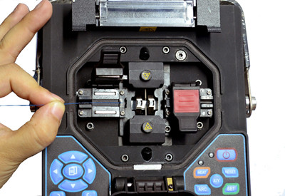
Fusion splicing machines are usually called fusion splicer available on the market that splice a single fiber or a ribbon of 12 fibers at one time. The above picture shows how to splice a fiber optic jumper. Virtually all single-mode splices are fusion. Fusion splices are made by "welding" the two fibers together usually by an electric arc. To be safe, you should not do that in an enclosed space like a manhole or an explosive atmosphere, and the equipment is too bulky for most aerial applications, so fusion splicing is usually done above ground in a truck or trailer set up for the purpose.
Today's single-mode fusion splicers are automated and you have a hard time making a bad splice as long as you cleave the fiber properly. Fusion splicers cost thousands US dollars (up to $5,000), but the splices only cost a few dollars each. The following part display the main features of the fusion splicing:
- Typical average optical losses of 0.05dB or lower
- Not de-mateable
- Special installation skills needed
- Tools sensitive to the environment
- Relatively long installation time
- Standard organizer techniques required
Pre-terminated System
Pre-termination is the alternative termination method popular on the market. Cables and fibers are terminated to a connector in the factory. When carefully planned, splicing jobs for specialized technicians can be limited to the network construction phase. But provisioning, churn and network testing can be performed by technicians without specific fiber skills, because the organizers can be very simple.
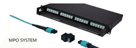
With pre-connectorized products, the connection time is reduced from 20 to less than 5 minutes, including the connector cleaning step. When connecting fibers with connector technology, there is no issue of environmental sensitivity. What’s more, connectors are accessible on the outside of the network element, reducing the need to access a product and the risk of disturbing other lines. The image below shows the MPO pre-terminated cables.
Factory pre-termination is also compatible with optical budget requirements by selecting the appropriate grade as defined by the international IEC standards. When properly planned, pre-connectorized
products do not add extra connectivity points, thus eliminating extra optical loss or reflections. In all, the most obvious features of the pre-terminated system lies in the following part:
- Typical losses of 0.15dB or less
- Fully de-mateable
- No special installation skills required
- Reduced installation time
- Very simple organizer systems
- Insensitive to environmental conditions
Cost Comparison
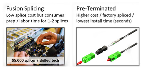
The start-up costs for the fusion splice are significantly higher, as fusion splicers can be very expensive. Even the cheapest fusion splicer will cost nearly $2,900 (FS-F600 Fusion Splicer from FS.COM) more than the most expensive crimp kit. Not counting the initial start-up costs, splices will run anywhere from $7.20 to $8.25 per splice, which is much lower than the pre-terminated connector. The following image shows the vivid comparison between fusion splicing and pre-terminated system.
As for the pre-terminated connector, the most significant advantage is the wire management hardware involved. A pre-terminated connector requires no additional hardware over a standard connector. And it is faster to terminate a crimp connector, saving labor time ($0.75 per splice), and splicing also requires additional material costs in the form of splice protectors ($0.40 per splice). Fiber splicing technicians have specialized training that makes them expensive when compared to someone simply plugging things in. The additional material and closet space for managing splices can cost an additional $6.05-7.10 per connector. But with a little careful planning as to lengths of fibers needed, pre-terminated fibers can be installed quickly and with no training.
In all, fusion splicing makes a lot of sense for trunk fibers and locations where there are anywhere from 48 to 192 fibers to splice. In the drop locations, where there may be only one or two splices at each location, the setup time for each location may negate any cost savings from fusion splicing.
Making the Choice
In comparing pre-termination and fusion splicing, both have their inhered advantages. Fusion splicers offer many advantages in the premises environment, from being lightweight and compact to operating on a battery. These new units minimize setup time and are ideal for use in locations where space is tight. In addition, the total splice and heater cycle time is less than one minute, thereby enabling technicians to move through many termination locations quickly.
However, we cannot deny the fact that the start up cost of the fusion splicing is huge, thus customers that can’t deal with budget are going to demand pre-terminated connectors. Pre-terminated solutions offer the most benefits: It’s easy to install pret-terminated cables, and because they’re available in custom lengths, it’s easy to get the exact lengths required to limit the excess slack. Many more users will rely on the pre-terminated trunk cables and sacrifice the inconvenience of dealing with slack, because it offers faster deployment.
As you get into significantly higher fiber counts, fusion splicing could save time over installing connectors. While for those who don’t have a fusion splicer or splicing experience, may want to consider pre-terminated connectors. FS.COM offers both fusion splicer and per-terminated cables, our products are integrated, holistic physical infrastructure solutions that guarantee a reliable and stable performance for your network. Please contact us if you need help.
Oznake: Fusion Splicing, Pre-terminated, wire management, fiber optic jumper
komentiraj (0) * ispiši * #
Cable Plant Used in a Fiber Optic Data Link
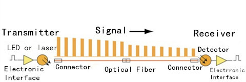
petak , 29.07.2016.A fiber optic data link carries signals for communications, security, control and similar purposes by using transceivers and optical fibers. Designed to protect the fibers, an optical fiber cable should be installed, spliced and terminated with the proper hardware to mate the data link transceivers, and included in a fiber optic cable plant. This cable plant must be selected and installed to withstand the environment, and typically terminated at outlets or patch panels near the communications equipment. It’s connected to the transceiver by short fiber optic jumper. Last blog introduces fiber optic data links: parts, signals and power budget. Today’s blog details another device used in data links: fiber optic cable plant.
Cable Plant Basicst Basics
Since the fiber optic cable plant consists of the optical cable which is terminated with the transceiver, this cable plant must be compatible with the performance parameters of the transceivers for the link to operate properly. This includes types of fiber capped with different connectors (e.g. LC to SC fiber patch cable), optical loss and bandwidth of the cable plant. For the cable plant, a loss budget must be calculated to estimate its loss and a power budget to determine if the planned communications system will operate over the cable plant.
Cable Plant Performance Factors Factors
For a fiber optic data link performances, the parameters are those that define the communications signals to be carried on the link or bandwidth at which the link operates, the length of the link and the specifications (bandwidth and optical loss) of the fiber optic cable plant. These factors determine the types of transceivers and cable plant components that must be chosen for a communications system. (Among these factors, the loss of the cable plant and the bandwidth have effects on the link design and testing after installation.)
Cable Plant Lossant Loss
The loss of the cable plant is determined by the summation of the loss in the cable plant because of fiber attenuation, splice loss and connector loss. In some cases, the fiber attenuation may be increased due to improper installation of the cable. As a signal travels down the fiber, the signal will be attenuated by the optical fiber and reduced by the loss in connectors and splices.
Loss Budgets Budgets
For each cable plant designed, the loss budget must be calculated. Then according to the loss budget, the loss of the fiber in the cable plant can be estimated by multiplying the length (km) by the attenuation coefficient (dB/km), then adding the loss from connectors and/or splices determined by the number of connectors and/or splices times the estimated loss each to get the total estimated loss of the cable plant. The cable plant loss budget must be lower than the power budget of the link transceivers (see below) for the link to work properly.
Dispersionspersion
Dispersion or pulse spreading limits the bandwidth of the link. Transceivers have some dispersion caused by the limitations of the electronics and electro-optical components, but most of the dispersion results from the limited bandwidth of the fiber in the cable plant.

Dispersion in multi-mode fiber (MMF) occurs by modal dispersion or chromatic dispersion. Modal dispersion is caused by the different velocities of the various modes being transmitted in the fiber. Chromatic dispersion is caused by the different velocities of light at different wavelengths.
Single-mode fiber (SMF) also causes dispersion, but generally only in very long links. Chromatic dispersion has the same cause as MMF, the differences in the speed of light at different wavelengths. SMF may also suffer from polarization-mode dispersion causes by the different speeds of polarized light in the fibers.
The transceiver must be chosen to offer proper performance to the communications system’s requirements for bandwidth or bitrate, and to supply an optical transmitter output of sufficient power and receiver of adequate sensitivity to operate over the optical loss caused by the cable plant of the communications system. The difference in the transmitter output and receiver sensitivity defines the optical power budget of the link.
The cable plant components, optical fiber, splices and connectors, are chosen to allow sufficient distance and bandwidth performance with the transceivers to meet the communications system’s optical power budget requirements. The power budget of the link defines the maximum loss budget for the cable plant. The maximum link length will be determined by the power budget and loss budget for low bit rate links that will be derated for dispersion for higher bandwidth links.
Most communications systems with short links have options for both MMF and SMF, while longer links use only SMF. All networks may provide guidance as to the types or grades of fiber needed to support certain applications.
Every manufacturer of data links components and systems specifies their link for receiver sensitivity (perhaps a minimum power required) and minimum power coupled into the fiber from the source. In order for a manufacturer or system designer to test them properly, it is necessary to know the test conditions. For data link components, that includes input data frequency or bitrate and duty cycle, power supply voltages and the type of fiber coupled to the source. For systems, it will be the diagnostic software needed by the system.
Conclusionnclusion
Fiber optic cable plant is an integral part of a fiber optic data link, and it should be managed in the exact path that every fiber in each cable follows, including intermediate connections and every connector type.
Oznake: fiber optic data link, cable plant, transceiver, fiber optic jumper, optical cable, LC to SC fiber patch cable
komentiraj (0) * ispiši * #
Proper Management of Fiber Patch Cord
srijeda , 01.06.2016.Past several years has witnessed a rapid deployment of fiber optic patch cables in optical communication networks. Compared with electrical cables, fiber patch cords (or called fiber optic jumper) are designed with enormous bandwidth capabilities, which make them preferred in digital and analog data transmission. These jumpers are fiber optic cables that are terminated at each end with connectors that plug into various pieces of equipment, available in single-mode and multi-mode patch cord versions (with OM3 patch cable widely used for short-reach transmission).
As fiber optic technology develops, the installation of fiber patch cords becomes increasingly easy nowadays. But to guarantee smooth networking performance, the proper patch cable management is essential. With proper management, it’s simple to go on cable operation and maintenance, saving time and cost. This article mainly discusses five factors that need to be considered during patch cord management.

Kinks, snags, pinches and poor contacts can dramatically reduce the performance of a fiber patch cord. The following factors are important in avoiding these problems.
Bend Radius
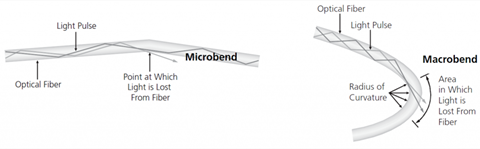
Since fiber optic cable made of glass has a fragile core, it requires great care and attention to avoid breaking this core during cable termination and operation. And in no case is fiber’s bend radius allowed. The minimum bend radius for patch cords varies with cord diameter. For 1.6mm and 3.0mm cords, the minimum un-loaded bend radius is 1.4 in (3.5cm), and for InstaPATCH Plus MPO patch cords, the minimum bend radius is ten times the cord diameter. If a fiber cable is bent excessively, the optical signal within the cable may refract and escape through the fiber cladding which will cause a loss of signal strength and is known as bend loss.
In addition, bending, especially during the installation and pulling of fiber patch cable might also cause micro cracks, and damage the fiber permanently. Generally, there are two basic types of bends in fiber, which are microbends and macrobends, with the latter larger than the former (as is shown below).
Patch Cord Path
This factor is closely related to the bend radius. The patch cable path should be clearly defined and easy to follow. Improper cable routing can lead to increased congestion in the termination panel, increasing the possibility of bend radius violations and possible failure in long-term. However, the well managed patch cable path ensures that bend radius requirements are maintained at all points, making accessing individual patch cable easier, quicker and safer. If the existing cord is the right length, it may be possible to re-use it. If this is the case, remove the cord completely and re-run it in through the cable pathways. This is the only sure way to ensure there are no tangles, kinks or strains in the cord.
Patch Cord Pulling & Stress
It’s not advised to use excessive force during the patching process, since too much force can stress cords and connectors, degrading their performance. If you need to use force in pulling a cord and there is something wrong, then stop and find the problem, and fix it before proceeding.
Patch Cord Accessibility
If the installed patch cable is easy to be accessed, the maintenance and operation would be quick without inducing a macrobend on an adjacent fiber. Accessibility is critical during network reconfiguration operations and directly impacts operation costs and network reliability.
Physical Protection
Patch cords that are routed between pieces of equipment can largely affect network reliability. Without proper protection, they would be easy to be damaged by technicians and equipment accidentally. Thus, physical protection of the installed patch cords is very important.
After discussing patch cord management, hers is another notice. Patching patch cord is critical in the first time, since its mistakes may cause disruption. Thus, after managing patch cord, taking time to make a final visual check on connections is a good investment. When patch panels are mounted in enclosures, ensure these are securely closed and, where necessary, locked, making sure that cord slack is not snagged or pinched by the doors.
Conclusion
Proper management of fiber patch cord can help to decrease operating costs and the time required to turn-up or restore service, making the operation reliable and flexible. As a professional fiber patch cord manufacturer, Fiberstore Cable Management provides ideal solutions for the distribution of cables and access to power, data and communication services on the wall and under the floor and for pole. Keep in mind those above-mentioned five factors, then the proper cable management is halt-succeeded.
Oznake: fiber optic patch cables, fiber optic jumper, OM3 patch cable, fiber patch cord manufacturer, cable management
komentiraj (0) * ispiši * #
Three Useful Fiber Patch Cords and Their Use
petak , 27.05.2016.With the rapid advancement of fiber optic technology and trend towards optical communications, fiber optic patch cord has realized its great use in high speed data transmission networks, found in routers, fiber patch panels, media converters and even in hubs and switches. Compared to its previous counterpart, fiber optic jumper causes lower signal loss, delivers more bandwidth and carries more information, becoming more and more popular in cabling installation or upgrading between or inside buildings. Just like the transceiver modules which fall in many types based on different standards, fiber optic patch cables are also available in several kinds, including single-mode/multi-mode, simplex/duplex, MPO/MTP cable, armored patch cord, and so on. This article aims to introduce the last three useful fiber patch cords and their use.
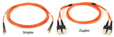
Simplex/Duplex Patch Cables
Simplex cable, also known as single strand cables, has one fiber, tight-buffered (coated with a 900micron buffer over the primary buffer coating) with Kevlar (aramid fiber) strength members and jacketed for indoor use. The jacket is usually 3mm (1/8 in.) diameter, but some 2mm cable is sometimes used with small form factor connectors. Duplex (zipcord) cable has two fibers joined with a thin web.
Since simplex patch cord consists of only one fiber link, it’s used in such applications that only require one-way data transfer. But when the equipment can transmit and receive on two different wavelengths, simplex cable can also be considered. For example, transmit could be at 1310nm and receive could be at 1550nm. This application is found more with single-mode simplex patch cable.
Duplex patch cable is suitable for applications that require simultaneous, bidirectional data transfer. Typical applications include workstations, fiber switches and servers, Ethernet switches, backbone ports, and similar hardware.
MPO/MTP Cable
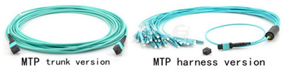
MPO/MTP cable uses multi-fiber MPO/MTP connectors for setting up high-performance data networks in data centers, so as to achieve greater bandwidth and handle network traffic requirements. Specifically, in MPO/MTP cable component, each one of the connector are used with ribbon type fiber optic cables which contain multi-fiber in one single jacket, so that MPO/MTP patch cord greatly saves space, very convenient to use. Based on single ferrule MT technology, the MPO/MTP cable assemblies are able to provide up to 72 fiber connections in a single point, reducing the physical space and labor requirement, while providing the same bandwidth capacity of a multi-fiber cable with individual fiber connector terminations per cable. MTP cables can be divided into trunk and harness versions (image below).
MPO/MTP patch cables have great use in Gigabit applications, especially in 40GbE. Often, MPO/MTP connectors terminate OM3 or MO4 to form structured cabling, serving as the transmission medium for 40GBASE optics (ie. QFX-QSFP-40G-SR4).
Armored Patch Cord
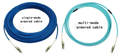
Armored patch cord enjoys all the features of standard fiber patch cord, available in single-mode and multi-mode version (shown below), except its much stronger characteristic. It won’t get damaged even it is stepped by an adult. What’s more, this kind of patch cord is anti-rodents, and when it’s utilized, people do not need to worry that the rodent animals like the rats may bite the cables and make them broken. Although armored fiber cables are strong, they are actually as flexible as standard fiber jumper cords, and they can be bent randomly without being broken.
Armored patch cable can be made with the similar outer diameter to the standard patch cable, which makes it a space-saving design. In addition, armored fiber cables can be with different jacket colors and jacket types, like OFNR. Light in weight, armored fiber patch cords can be with SC, ST, FC, LC, MU, SC/APC, ST/APC, FC/APC, LC/APC types of terminations.
The armored fiber optic patch cords are more robust designed, suitable to be deployed in FTTH projects inside the buildings. They use stainless steel armor inside the jacket to be resistant of high tension and pressure, able to resist the weight of an adult person.
Conclusion
Fiber optic patch cables are of great use in various conditions from local area network to airplanes, especially in communication networks in which the importance of patch cords is even more obvious. To get the high-quality patch cords, you can choose Fiberstore, which supplies a wide range of cables, including simplex/duplex, MPO/MTP cable, armored patch cord discussed in this text. Other cable types, such as push-pull patch cords, and 10G SFP+ DAC cable, are also available. If you would like to buy such a product, you can visit Fiberstore directly.
Oznake: fiber optic patch cord, fiber optic jumper, simplex/duplex, MPO/MTP cable, armored patch cord, push-pull patch cords, DAC cable
komentiraj (0) * ispiši * #
