How to Deal With the Cable Spaghetti
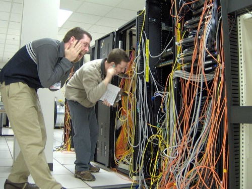
petak , 30.09.2016.Everyone loves a plate of delicious spaghetti, but everybody hates when network wires become so tangled that it looks like spaghetti. Even for seasoned network cabling installers or system administrators, cable spaghetti isn't only assaulting to their eyes and dignity, it can actually impede the ability to troubleshoot IT issues. People who had the experience of re-cabling or organizing the cable spaghetti, they may understand that prevent your network from being confused with spaghetti usually takes regular planning and maintenance. Otherwise, it will drive you to the blink of insanity, just as the engineers in the picture. Here are what you should know about the best practices that will prevent from bad spaghetti.
Use Appropriate Cable Length
Every cable installer might have the experience. It is a nightmare to use a 25-foot cable or longer one to connect two severs that only five feet from each other, so the extra length will lead to major spaghetti problems in the future. Additionally, excess cable becomes a trouble to manage in a high density fiber cable management because when there is too much cable, there's no where to put it. Invest in the right size cable, and your racks will be much more manageable. Just take the time to measure your cables and only using the exact length that you need, not only will it make your server room look organized, but it will also increase overall efficiency.
Bundle the Cables
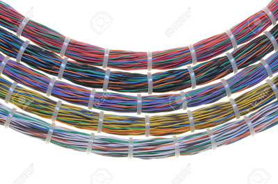
When making large horizontal or vertical runs, bundling the cables together makes them look nice and clean. Using cable ties, or wraps will keep the cables together. You can also use them to attach your cable bundle to infrastructure pieces.
Run Cables in Channels
Instead of stringing cables randomly between devices, create a clear pathway for the cables to follow. For all cables leaving the rack, have them climb up the outer wall of the rack, cross over, crawl down the other rack, fan out horizontally and plug in.
Label Your Cables
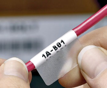
When first installing cables or cleaning up, always remember to label every single cable on the rack. This step adds a few extra minutes of labor to the installation, but it will save you a major headache in the long run. For example, if you want to upgrade to higher bandwidth, you will have to unplug a bunch of wires and replace some new cables. having labels on them allows you to immediately know where to plug them back in.
Take the Future Proof into Account
A man without distant care must have near sorrow, this saying is also applied in the cable installation. If you install your network infrastructure that only covers your current needs, then you will be facing a spaghetti situation in the future when it comes to add more wires into full conduits. Thus to avoid this problem, you are supposed to carefully planning out your network, and position existing and future equipment in spots that will use less cable length and have minimal overlap.
Don't Forget Bend Radius
Bend radius is the maximum angle that a cable can be bent. If you over-bend cables, they will break or become damaged. Then they will not function properly. This is especially true for fiber cables, which can be sensitive to bends. Proper cable management will keep your infrastructure functioning by maintaining proper bend radius.
How to Tackle the Bad Cable Spaghetti
- Admit the problem—It's tempting to loosely string a cable from point A to point B. It's quick, easy, and you don't have to deal with the real issues. But you're only hurting yourself. The next time you need to make a patch, commit to doing it the right way. It will pay off in the end.
- Clear your schedule—Now that you are no longer contributing to the problem, it is time to check your calendar. Block out a large chunk of time to clean up the mess. Oftentimes, you will need to work whenever the office is empty since users could lose connectivity to the network.
- Make a list of supplies—Having the right accessories is essential to a job well done. If you have the correct supplies, it's easier to clean up and keep your site organized. The rack clean up essentials include: cable management, cable ties, finger nail clippers, scissors, labels, horizontal management, vertical cable management.
- Just go for it—The final step is to bite the bullet and just start. It won't get any easier than it is today. Assemble your supplies, set the date and go for it. You will thank yourself later.
Conclusion
To sum up, this article recommends several tips for preventing from cable spaghetti for your data center solution. Besides the above suggestions, there are two overarching themes that you should bear in mind—do not take shortcuts and careful planning. FS.COM as a rising telecommunication manufacturer, will work closely with your business to understand your needs and come up with a network layout that will handle your growth. Our cable management accessories like cable ties, wire Loom, cable lacing shelf, D-Ring cable manager etc., are all provided. If you have any requirement, please send your request to us.
Oznake: Cable Spaghetti, data center solution, fiber cable management
komentiraj (0) * ispiši * #
Introduction to HPE 40G Optics
ponedjeljak , 26.09.2016.Recently the increasing network infrastructures are upgrading to 40GbE to ensure better performance, which greatly promote the popularity of 40G optical devices, especially the 40G optical transceivers and 40G QSFP+ cables. 40G optics, featured by its unique specification, are designed to meet different connectivity applications in data center. Telecom vendors like HPE, Cisco, Juniper, Arista are offering all types of 40G optics to meet the market needs, of which 40G optics form HPE are the commonly used products on the market. This article will have a short introduction to the HPE 40G modules and DAC cables.
Shedding Light on HPE 40G QSFP+ Modules
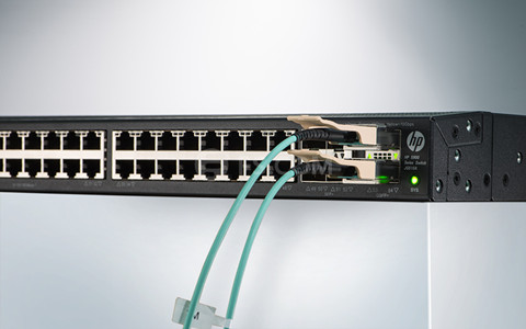
The 40G QSFP+ module is a compact, hot-pluggable transceiver used for data communications applications. It supports Serial Attached SCSI, 40G Ethernet, QDR (40G) and FDR (56G) Infiniband and other communications standards. Compared with SFP+ modules, QSFP+ transceiver increases the port-density of 3-4 times. The following part will mainly introduce three different types—40G LR4 QSFP+ transceiver, 40G SR4 QSFP+ transceiver and 40G CSR4 QSFP+ transceiver. Figure 1 shows a QSFP+ modules plugging into a HPE switch.
- HP 40GBASE-LR4 QSFP+ Transceiver
The 40G LR4 QSFP+ transceiver enables high-speed 4x10G operations and can be interoperability with 10GBASE-LR interfaces. Together with the LC connector, it can support an optical link length up to 10 kilometers over single-mode fiber. 40G QSFP+ cable is compliant with QSFP+ MSA and IEEE 802.3ba. In order to realize the function of transmitting 4-channel signals over single-mode fiber, this transceiver has to introduce MUX/DEMUX to multiplex/de-multiplex optical signals.
- HP 40GBASE-SR4 QSFP+ Transceiver
The 40G SR4 QSFP+ transceiver compatible with the 802.3ba 40GBASE-SR4 standard, provides a 40G optical connection using MPO/MTP fiber ribbon connectors. Unlike the 40G LR4 QSFP+ transceiver, this transceiver are used together with multimode fiber, supporting with a link length up to 100 meters on OM3 cable and 150 meters on OM4 cable. Take HPE JG325B as an example, it supports link lengths of 100m and 150m, respectively on OM3 and OM4 multimode fiber at a wavelength of 850nm. It primarily enables high-bandwidth 40G optical links over 12-fiber parallel fiber terminated with MPO/MTP multifiber connectors and can also be used in a 4x10G module for interoperability with 10GBASE-SR interfaces.
- HP 40GBASE-CSR4 QSFP+ Transceiver
40GBASE-CSR4 QSFP extends the reach of IEEE 40GBASE-SR4 interface to 300 and 400 meters on laser-optimized OM3 and OM4 multimode parallel fiber, respectively. Each 10-gigabit lane of this module is compliant to IEEE 10GBASE-SR specifications. This module can be used for native 40G optical links over 12-fiber parallel cables with MPO/MTP female connectors or in a 4x10G mode with parallel to duplex fiber breakout cables for connectivity to four 10GBASE-SR interfaces.
Features of 40G HP QSFP+ Modules
- Hot-pluggable input/output device that plugs into a 40 Gigabit Ethernet QSFP port
- High-speed electrical interface compliant to the IEEE 802.3ba standard
- Certified and tested on QSFP 40G ports for superior performance, quality, and reliability
- Digital Diagnostics Monitoring Interface
In addition, QSFP+ modules provide 40Gb/s Ethernet data rates over MMF optic cable and SMF optic cable. QSFP+ modules taking up very little space on a switch or server interface, allowing vendors to provide multiple QSFP+ ports in the same space. Besides the QSFP+ transceivers, HPE also offers QSFP+ cables for interconnection, which will be introduced in the next part.
HP 40GbE QSFP+ Cables
HPE offers a variety of 40GbE optical devices, such as QSFP to Four SFP+ copper breakout cables, QSFP to Four SFP+ active optical breakout cables, QSFP to QSFP active optical cables, etc. Each has its unique characteristics. Take HPE QSFP+ breakout cable as an example, compatible HPE JG330A (QSFP+ to 4SFP+ Passive Copper Cable) is very suitable for short distances and offer a very cost-effective way to establish a 40-gigabit link between QSFP port and SFP+ port of HPE switches within racks and across adjacent racks.
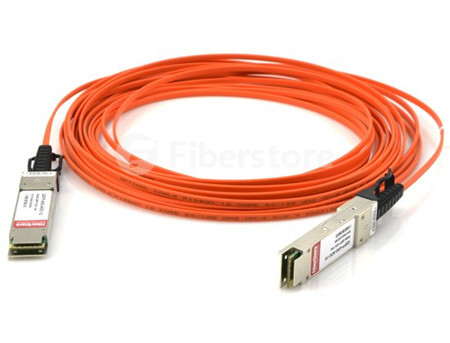
HPE QSFP+ to QSFP+ active optical cables are suitable for 40G Ethernet. And there are two common active optical cables available on the market—QSFP to 4 SFP+ breakout AOC and QSFP to QSFP AOC (see in the above image). QSFP to 4 SFP+ breakout AOC is a 4×10 Gb/s parallel active optical cable that transmits four separate streams of 10 Gb/s data over ribbon cables in a point-to-multipoint configuration. This cable contains a QSFP+ module on one end and four separate SFP+ modules at the other ends. The latter is a 40 Gb/s parallel active optical cable which transmits error-free parallel 4×10 Gb/s data over multimode fiber (MMF) ribbon cables.
Choose Compatible HPE Transceiver Modules
The first factor that forces people to choose third-party transceiver modules other than original modules is budget. Because the price of the original products is usually three or four times higher than 3-rd party devices. Designers can’t afford it. In addition, the third-party transceiver modules offered by reliable vendors are guaranteed to be well-tested and fully compatible with the major brand. It is feasible to buy compatible HPE transceivers from reliable OEM vendors. For example, FS.COM is devoted to design, manufacture, and sell a broad portfolio of optical products, including compatible HPE 40G QSFP+ transceivers. We supply high quality QSFP+ transceivers which are used primarily in switches, routers, and data center equipment.
Oznake: HPE 40G Optics, 40GbE, 40G QSFP
komentiraj (0) * ispiši * #
Do You Have Any Idea of Water-Resistant Fiber Optic Cable?
srijeda , 21.09.2016.There is no doubt that fiber optic cables play an integral role in telecommunication industry. Applications like data centers, local area networks, telecommunication networks, industrial Ethernet, and wireless network are all needing fiber optics to ensure smooth connectivity. Each application requires a specific cable design based on performance requirements, environmental conditions, and installation type. The common fiber optic cables like LC to LC patch cord cannot adapt to the harsh environment (e.g. moisture environment or underground deployment), thus water-resistant fiber optic cables are highly demanded on the market due to their water proof nature. Here is what you should know about the water-resistant fiber optic cable.
Overview of Water-resistant Fiber Optic Cables
Water-resistant fiber optic cable refers to the special type of fiber optic cable that are designed and specified for installations where the cable will come in contact with water or moisture, such as aerial, direct buried, or in conduit. The cables in these applications are exposed to or can be temporarily submerged in water, so they contain either a water-resistant gel-filled or gel-free (dry gel) polymer.
Generally, fiber optic cables can be divided into three types—outside plant cable (OSP), indoor/outdoor, and indoor, which are specified based on the environment and location where they are installed. With the exception of indoor cables, all cables contain water-resistant gel-filled or gel-free material to protect them from water and moisture. Before the use of gel-filled and gel-free materials, flooded core was another water-blocking method that is rarely used today (it has been replaced with gel-filled). The following image shows the gel-filled cables.
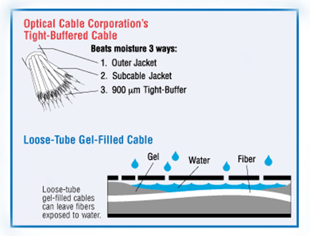
The gel is a gooey substance that must be removed when accessing and installing the cable. Gel-free cables, which are now more widely used, contain a super-absorbent polymer powder that is activated when it comes in contact with water or moisture. This blocks the water from penetrating the cable and allows for some expansion and contraction with temperature changes. Indoor cables do not contain water-resistant material since they are not typically exposed to water. Indoor (and indoor/outdoor) cables must meet additional flammability requirements dictated by local codes, such as the National Electrical Code.
Tight-Buffered & Loose Tube Cable Construction Provides Excellent Moisture Resistance
Water-resistant materials and cables are included in many industry specifications and standards. Generally, there are two basic water-resistant cable designs: Tight-buffer cables (primarily used inside buildings), Loose tube cables (used for OSP and indoor/outdoor).
It is known to all that most tight-buffered cable designs (seen in image below) are specified for indoor use, but some of them are designed with water-resistant powder and yarn, making them suitable for some indoor/outdoor applications. This tight-buffered cable utilizes an different design approach to deal with the moisture issue. Buffer materials are low-porosity plastics with excellent moisture resistance. This construction very effectively minimises the water molecule and OH-ion concentration level at the glass surface and virtually eliminates the stress corrosion phenomenon.

In loose tube cables (seen in image below), in order to prevent the water from reaching the 250Ľm coated fibers, the tubes surrounding the fibers must be filled with water-absorbent powder or gel that withstands high-moisture conditions, making them excellent for outside plant applications. This approach is especially made to waterproof the cable by filling the empty spaces in the cable with gel. The gel-filled tubes can also expand and contract with temperature changes, which makes loose-tube cable great for harsh, high-humidity environments where water or condensation can be a problem. However, gels can move, flow, and settle, leaves an uncertainty of the filled level of any particular point of a loose-tube gel-filled cable. Because loose-tube cable is typically 250 microns, you'll need a fan-out kit to build up the individual fiber strands to 900 microns when making the transition at the entrance point from outdoor loose-tube to indoor to tight-buffered cable.
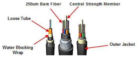
The same level of protection remains in place all along the fiber, regardless of installation conditions, environment, or time. The balance of the tight-buffered, tight bound cable designs is such that it minimizes the open spaces available in the cable structure in which water can reside. Even if an outer cable jacket is cut, or water otherwise enters the cable structure, only a very small percentage of the cross-sectional area is open to water.
Conclusion
When selecting the suitable fiber optic cables, one must consider the application, the installation location, and the appropriate cable design and type according to specifications and standards. The water-resistant optic cable is specially made for moisture environment to insure the smooth connectivity. However, whether to have the loose tube fiber optic cable or tight buffered cable, it depends on the installation location. FS.COM offers a full range of fiber optic cables at very economical rates. These cables are widely used and are highly demanded on the market due to their water proof nature. In addition to this, we offer these cables in various fiber optic cable specifications, such as duplex/simplex fiber cable, single-mode/multimode fiber optic cable, LC/FC/SC/ST fiber optic cable and so on. LC to FC patch cord is absolutely high quality and low price, just as the other fiber optic cables. If you want to know more about our products, please contact us directly.
Oznake: Water-Resistant Fiber Optic Cable, LC to LC patch cord, LC to FC patch cord
komentiraj (0) * ispiši * #
Understanding Industrial Fiber Optic Cable
ponedjeljak , 19.09.2016.Fiber optic cabling usually utilizes ruggedized jackets to ensure optimal performance in the face of extreme temperatures; exposure to UV/sunlight, oil, and solvents; and crushing impact, which makes it the ideal solution in any industrial environment where high-speed, high-bandwidth data solutions are needed. It can be used for campus and in-building data backbones to anchor an operation’s Ethernet, and also for point-to-point digital signal transmission. Today’s article will make a brief introduction to the basics of industrial fiber optic cable.

The Advantages of Fiber Optic Cable
Compared to the conventional copper wires, fiber optic cables are smaller and lighter than copper cables, extremely durable and intrinsically safe, with no risk of spark hazards. In addition, the following part lists several detailed information about the benefits of fiber optics.
- Higher carrying capacity—as the fiber optic cables are thinner than copper cables, more fibers can be bundled into a given-diameter cable. This allows more data information will be be carried across the network without interruption.
- Less signal degradation—it is known that the loss of signal in optical fiber is less than in copper wire.
- Lightweight—An optical cable weighs less than a comparable copper wire cable. Fiber-optic cables take up less space in the ground.
- Flexible—Because fiber optics are so flexible and can transmit and receive light, they are used in many flexible digital applications.
Types of Fiber Optic Cables
Fiber optic cabling can be segmented based on design criteria and installation environment:
Loose tube cables lay thinly coated fiber strands into unitized thermoplastic tubes, giving the fiber strands flexibility to move within the tubes and the cable, which makes it possess the ability to stand up to outdoor temperatures and harsh environments. Although loose-tube gel-filled fiber optic cables are used for high-fiber-count, long-distance telco applications, they are an inferior design for the Local Area Network applications where reliability, attenuation stability over a wide temperature range and low installed cost are the priorities.

Tight buffered cables contain an individual buffer on each fiber stand, allowing for easy handling and quick termination. For common small fiber counts, this design delivers a smaller cable diameter than loose tube cables and is best suited for indoor environments. The most common designs for tight buffered cabling are distribution and breakout. For applications like moderate distance transmission for telecom local loop, LAN, SAN, and point-to-point links in cities, buildings, factories, office parks and on campuses. Tight-buffered cables offer the flexibility, direct connectability and design versatility necessary to satisfy the diverse requirements existing in high performance fiber optic applications.
Singlemode and multi-mode cables are another common types of fiber optic cables. Single-mode fiber strands are designed to interface with laser optic light sources for distances beyond 300 meters, while multi-mode strands or MM fiber patch cords are designed to interface with LED and vertical-cavity surface emitting laser (VCSEL) light sources for short-distance cabling runs.
Considerations When Installing Fiber Optic Cables
If you are considering using fiber optic cables in your installation, take a moment to review the installation guides. Firstly, for industrial installations, it is critical to consider and evaluate the environment. Additionally, as the fiber optic cables are more susceptible to damage during the stress of installation, therefore there are two specifications for bend radii—Bend Radii before installation and Bend Radii after installation. All hardware and support structures should follow the recommendations of TIA-569 and NECA/BICSI 568 Standards documents. Last but not the least, use cable management straps or cable ties to support cable bundles. Make sure these implements are fastened snugly, but not tightly around cable bundles.
Conclusion
There is without saying that the advent of fiber optic cable solutions has been one of the best things to happen to technology in recent years. With the demand on technology ever-increasing, fiber optic cables are becoming the preferred method of transmission over traditional coaxial solutions. FS.COM offers a full range of optical devices, such as fiber optic cable, optical transceivers, DAC/AOC cables and so on. Fiber patch cables LC to LC and LC LC single mode patch cord are provided with high quality and low price. If you have any requirement, please send your request to us.
Oznake: fiber optic cable, Fiber patch cables LC to LC, LC LC single mode patch cord
komentiraj (0) * ispiši * #
Do You Know About Cat 8 Cable?
srijeda , 14.09.2016.Cat 5e or cat 6 cables now are the mainstream of the copper network solution, but optical technology are progressing to promote higher category copper cables for the increasingly heavy-loaded data center solution. Cat 8 cables lately has been much talked about, especially after the TIA category 8 cabling standard approved. Category 8 is regarded as the next-generation twisted-pair cabling specification for higher data rate, but it is still under development. Here is what we need to know about the basics of Cat 8 cabling.
Main Features of Category 8 Standard
Cat 8 cable is especially designed to support 25G or 40G Ethernet data rate with a link distance of up to 30 meters, which is sufficient for most switch-to-server connections for top-of-rack (ToR), middle-of-row (MoR) or end-of-row (EoR) topologies. In addition, category 8 cabling is fully backward compatible with category 6A cabling, including RJ45 connectivity, and supports all Category 6A applications such as 10GBASE-T for a distance of 100 meters.

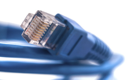
Category 8 cabling and components are specified with transmission performance of up to 2 GHz (four times the bandwidth of Category 6 cabling and two times the bandwidth of category 7) with more stringent alien crosstalk requirements. Meeting these requirements requires a shielded cabling system (F/UTP, S/FTP or F/FTP), just as seen in the above picture. What’s more, the cat 8 cables do not need more power to operate over shorter distances for 25GBASE-T/40GBASE-T application. The power needed to transmit a signal 30 meters at 40 Gb/s is approximately the same as the power needed for 10GBASE-T transmission for distances up to 100 meters.
How to Compare Category 8 to Those of Previous-Generation Twisted-pair Cabling Systems—Category 5, 6, 6A, 7, 7A?
The cat 5e cables was introduced in 1999 with the use of 100-meter, 4-connector channel in structure cabling. The primary differences between category systems is the frequency at which the signal is transmitted over the cable. Cat 6 cables are designed to support 10Gbqs with a frequency of 500 MHz. While Category 7/7A as n advanced version of cat 6 cables offers a 100-meter 4-connector channel using shielded cabling, and has been designed to transmit signals at a frequency of 1000 MHz. Even though Category 7/7A operates at the higher frequency, there is no corresponding improvement in data rate over Category 6A because 10GBase-T is still the fastest twisted-pair-based data rate recognized by IEEE 802.3.
Category 8 is a significant departure from previous systems in that it uses a frequency of 2000 MHz, and is limited to a 30-meter 2-connector channel. Unlike Category 5e or Category 6A, which could use either unshielded twisted-pair (UTP) or shielded cable construction, Category 8 will require shielded cabling. The most likely cable construction for Category 8 will be 22-AWG S/FTP cabling. Category 8 is also unique in that the ISO standard will recognize two different classes of product. Class I is based on the traditional RJ45 connector, while Class II will accept non-RJ45 connectors similar to Category 7/7A. While both solutions will offer backward compatibility in terms of transmitting the lower category data rates (1G or 10G), the Class I solution offers a migration path using the RJ45 connector platform. For example, a customer might install a Category 8 jack-to-jack link now, but continue to use Category 6A patch cords until the active equipment is upgraded.
Given Category 8’s Capabilities, Where Is It Most Likely to be Deployed?
Category 8 cabling is designed to support emerging IEEE 25GBase-T and 40GBase-T needed as server-to-access-switch interconnect applications. This need has been identified and available, or under development, over optical fiber links for longer reach (up to 500 meters), or twinax links for short reach (up to 7 meters).
The opportunity for balanced twisted-pair as a cost-effective viable media option for the intermediate distance needs between 5 and 30 meters, sufficient to serve 20 cabinets or racks in a data center, led to the initiation and development of both the IEEE 802.3 application standards and the associated TIA as well as ISO/IEC Category 8 cabling standards.
How to Install Category 8 Cables?
Category 8 will be a shielded, field-terminable, and with a very high bandwidth. Thus there to be at least some improvements made to how jacks are terminated in the field to both meet this new bandwidth and to ensure a good bond with the shield. Additionally, contractors must make sure that the cable is properly grounded. If the connector companies do their job right, grounding the Category 8 cables and connectors will be a seamless process for the installer, which is all based on the RJ45 connector. Any component qualified as a Category 8 component will also meet requirements specified for Category 6A and lower components.
Conclusion
Cat 8 product recently is not available on the market now, but it is believed that in the near future cat 8 related items will be ubiquitous. Cat 8 cabling are meant to support 25GBASE-T and 40GBASE-T specifications, which will greatly propel the development of 25G and 40G network. FS.COM will continue our efforts to stay in close touch with the latest technology and bring you the best products and services. We provide plenty of Cat 5/cat 6/ cat 7 components to meet your special requirement. Besides the copper cables, we also have the fiber optic cables terminated with several connectors like SC fiber patch cord, fiber patch cables LC to LC, LC to LC patch cord and so on. If you want to know more about our products, please sens your request to us.
Oznake: cat8 cable, Cat5e, Cat6, 10Gbase-T, 25GBASE-T
komentiraj (0) * ispiši * #
The basics of Ethernet
petak , 09.09.2016.In today’s telecom field, Ethernet has been utilized at various levels of the control hierarchy. Since Its standardization in 1980, Ethernet has become the most widely installed local area network (LAN) technology either in the office or the enterprise network for high-end controller. We talk about Ethernet every day, however, people without decades of experience can hardly say they know everything about Ethernet. Therefore, this article are here to provide a foundation of Ethernet basics to improve your understanding of networking in general.
What Is Ethernet?
Ethernet is the most widely used LAN technology that serves as one of the main methods for connecting a computer or network to an Internet hub. The origin of Ethernet was the idea of connecting several computers together in a network via coaxial cables; since that time it has evolved into a much more sophisticated system that uses specialized Ethernet cables that connect to a central hub or router to network several computers together. Modern technologies made it possible for Ethernet networks to span tens of kilometers but this doesn’t change the local nature of Ethernet. The picture below shows a network connection with router, hub and switch.
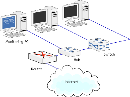
For users who have little experience in telecommunication field, they usually consider Ethernet as a synonym for Internet. In fact, these two terms are similar, but they are different from each other. Internet is global in its nature, while Ethernet is a LAN network. An Ethernet network allows many computers or optical devices to connect to one another, this is done with the help of special Ethernet hardware and Ethernet protocols, which will be explained in the below part.
Ethernet Hardware
Ethernet hardware are indispensable for the operation of Ethernet network. There are three main elements of Ethernet hardware: Ethernet cards, Ethernet cables, and Ethernet hubs and routers.
The Ethernet cards or adapter is the component that is plugged into the computer and the Ethernet cable connects them to the rest of the network. Owing to the Ethernet adapter, a computer can send and receive data packets from the other segments of the network and/or the Internet.
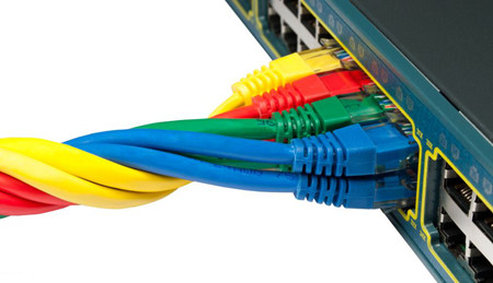
Ethernet cables is the medium that carries data in both packets to and from the computers, hubs, and routers in the Ethernet network. It usually comes in a number of styles, with the most common being Category 5, Category 5e or Category 6 cables. This type of cable are twisted copper cables that contain several wires which allow for the transfer of data in both directions to and from the computer. Cat 5e and Cat 6 cables are now the most commonly used Ethernet cable on the market. Network organizers are willing to turn to this copper cable rather than fiber jumper for its reliable performance and low cost. The following image shows the colorful category copper cables.
Ethernet hubs and Ethernet routers are the another important components of Ethernet network that mainly serves as a bridge to the internet. The router connects to the modem, which carries the Internet signal, sending and receiving data packet requests and routing them to the proper computers on the network. Even if a network isn't being used and only a single computer is present, in most cases that computer will connect to the modem by means of an Ethernet cable (or if a wireless router is being used, then the router will be connected to the modem). Hubs acts as a common connection point for devices in a network. It is used to connect segments of a LAN. When a packet arrives at one port, it is copied to the other ports so that all segments of the LAN can see all packets.
Ethernet Protocols
In addition to Ethernet hardware, another component that is required in order for Ethernet to work is a set of rules that define the communication within the Ethernet and with external networks. This set of rules is called Ethernet protocols, and there are tens of them used for communication within the Ethernet. As a network standard, each version of Ethernet includes specification for the physical network layer: how the signals will be sent and received. In order two devices on a network to be able to communicate successfully, it is mandatory that both devices use the same protocol. I cannot discuss all the protocols here, just take Carrier-Sense Multiple Access/Collision Detection (CSMA/CD) protocol as an example, which ensures that there are no collisions on the network and it is one of the most important Ethernet protocols.
Conclusion
What has been discussed in the above article is the basics of Ethernet knowledge including the definition, components and Ethernet protocols. Ethernet is such a big topic that it is not possible to be very detailed about it. But I still hope that this article about Ethernet basics is useful. FS.COM is a professional telecommunication manufacturer. Our optical devices are large in stock and can be shipped all around the world. Fiber optic cables like LC to SC patch cord, ST-LC patch cord, LC LC single mode fiber patch cable are provided at minimum prices. If you have any interest of today’s topic or any of our products, you can send your request to us.
Oznake: Ethernet, lan, Cat 5e, Cat 6, fiber optic cable, fiber jumper, LC to SC patch cord, ST-LC patch cord, LC LC single mode fiber patch cable
komentiraj (0) * ispiši * #
10G Data Center Cabling Solutions
srijeda , 07.09.2016.The rapid development in data center throughput has led to the increasing usage and demand for higher-performance servers, storage and interconnects. And the old 1G Ethernet cannot handle the heavy-loaded solutions in data center any more. As a result, datacenter designers are looking to the expansion of higher speed Ethernet solutions, specifically 10 G and 40G Ethernet. As for 10GbE, there are two broad categories—SFP+ optical options and 10GBASE-T available on the market, which pose difficulty in selecting the appropriate 10-gigabit physical media. This article will make a brief introduction to these two 10G solutions to help you choose the suitable one.
What Is 10G SFP+?
10G Small-form-factor pluggable plus (SFP+) is the industry standard for data rates up to 10 Gbps, which is also MSA compliant. SFP+ module is especially standardized for 10 Gbps application, and is identical in dimensions to the SFP. To achieve the SFP+ form factor reduction, only the optical-to-electrical and electrical-to-optical conversion functionalities occur inside the optical module. The key advantage of SFP+ over the existing 10 G optical interconnects is the higher port densities enabled by its dimensions, and lower power consumption. Figure 1 shows a SFP+ modules connected with a LC to LC patch cord.
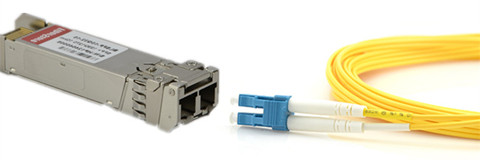
SFP+ transceivers are available in different 10G Ethernet standards—10GBASE-SR, 10GBASE-LR, 10GBASE-LRM, 10GBASE-ER, 10GBASE-ZR, 10GBASE-LX4 and 10GBASE-PR. Each standard has a unique specification that can be suitable for different applications. SFP+ optics are selected more often when designers need faster and more reliable solutions to handle 10 Gigabit Ethernet optical lines. With lower power usage and low latency, SFP+ ports are most commonly used for enterprise switches and also for plug-in cards for servers.
How Does 10G Copper Solutions Compare?
10G Ethernet can also run over twin-axial cabling, twisted pair cabling, and backplanes. SFP+ direct attach cable, 10GbASE-CX4 and 10GBASE-T are the common copper solutions for 10G short-reach interconnect. 10GBase-CX4 achieves the aggregate rate of 10 Gbps by transmitting over four independent cables at 3.125 Gbps. The disadvantage of this solution is the bulkiness of the cables that have eight twin-ax cables within them for a duplex link. And the bulkiness of the cables makes cable management more difficult. This becomes a significant limitation as the port densities and inter-port connection densities increase. Additionally, the number of conductors make these cables expensive compared to SFP+ cables.
10GBase-T enables 10 Gbps transmissions over Cat 6 and higher quality cables using complex signal processing and channel coding. The potential advantage of this technology is its extended reach. The extended reach and ability to enable structured cabling are not required for the short reach interconnects between servers and switches collocated in a rack. The disadvantages are its high power consumption and latency. The high latency in particular is a key limitation in latency sensitive data center and storage applications.
SFP+ Direct Attach DAC is another lower cost alternative to fiber with a limited link length of 7 meters. Additionally, it has significant power, cost, and performance advantages over the above media as explained below.
Why Use 10G DAC Cables in Data Center?
As 10 Gbps interconnects become ubiquitous in servers, providers are looking for a low cost, low power, and space efficient interconnect solution for the short reach (5-7m) links that dominate the data center environment. A length of seven meters covers all connections between server cards and switches, typically mounted on a single data center rack, and a vast majority of inter-rack connections. The SFP+ Direct Attach Copper is the 10G interconnect technology that matches these requirements, playing a vital role in enabling the next generation power and cost efficient data centers.
SFP+ Direct Attach Copper Solution
To further reduce cost and power in interconnect distances of 7 meters, which is sufficient to link server cards and switches, the SFP+ Direct Attach Copper replaces the optical modules and fiber with a passive copper cable with connectors identical to an SFP+ optical module. Figure 2 shows a SFP-H10GB-CU3M plugging in a Cisco switch. The reduction in cost and power are significant since the price of two optical modules required to support a full duplex link is approximately 10 times the cost of a fully connectorized SFP+ Direct Attach cable. In addition, the optical SFP+ modules consume around 1W each, adding 2W per port to the overall system power budget and cooling requirements.
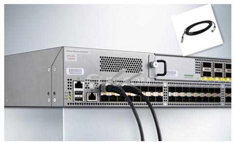
Data is transmitted as 10 G serial NRZ (Non Return to Zero) symbols with transmit pre-emphasis and receive equalization compensating for Inter Symbol Interference caused by the board trace and the copper cable. This choice of serial NRZ transmission over a passive medium makes SFP+ copper both a low power and low latency solution compared to its alternatives.
Conclusion
As more emphasis is placed on energy efficient data centers and higher bandwidth applications, the need for a small form factor, low power, low latency and low cost interconnect makes SFP+ Direct Attach the optimal solution for short-reach 10G interconnects. While SFP+ fiber options provides a great path for higher performance long haul applications. FS.COM is a top manufacturer for DAC Twinax cables (SFP+ Cables, XFP Cables, CX4 Cables, Infiniband Cables, etc) and best suppliers for QSFP+ products including 10G & 40G QSFP+ copper and AOC cables. Optics transceivers like QSFP+, SFP, SFP+, XFP, X2, XENPAK, SDH, Bidi are also offered. If you have any interest in our products, you can contact us directly.
Oznake: data center, 10G cabling, SFP, DAC cables, LC to LC patch cord, SFP-H10GB-CU3M
komentiraj (0) * ispiši * #
Deciding Between Passive Optical Networks and Active Optical Networks
petak , 02.09.2016.The FTTH solution is regarded as the best option with respect to the transmission quality and the bandwidth. The deployment of FTTH (Fiber To The Home) access networks has gone through a long way before subscribers use fiber cables instead of copper lines to achieve broadband Internet access. FTTH is a form of fiber-optic communication delivery with fiber extending from the central office to the subscriber's living or working space. The FTTH network can be directly laid by using active optical network (AON) or passive optical network (PON). Each design offers a way to separate data and set it upon its intended route to arrive at the proper place. These two networks comparatively have their advantages and disadvantages, which will be illustrated in the following article.
Passive Optical Network
A passive optical network (PON) is a point to multi-point (PMP) optical network that only uses fiber and passive components like optical splitters rather than active components (amplifiers, repeaters, or shaping circuits). That is to say, a passive optical network shares fiber optic strands for portions of the network. In passive optical system, a single fiber from a central office optical line terminal (OLT) is connected to optical network terminals (ONTs) or optical network units (ONUs) at customer premises. An optical splitter, also called PON splitter, is either fitted in or outside the subscriber’s premise to separate to collect optical signals and distribute the signals to users.
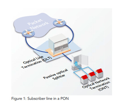
An OLT shown in the above image terminates the optical signals and distributes them to as many as 16 to 128 customers per fiber line. An optical network unit (ONU) terminates the PON at the customer’s home. The ONU usually communicates with an optical network terminal (ONT), which may be a separate box that connects the PON to TV sets, telephones, computers, or a wireless router. Note that the ONU and ONT are basically the same device.
Active Optical Network
The AON arrangement is a point-to-point structure (PTP), meaning that each user has his own dedicated fiber optical line terminated on an optical concentrator. In an active optical system, environmentally electrical switching equipment are deployed, such as a router or a switch aggregator, to manage signal distribution and route data to proper places. Additionally, AON is perfect for high-profit end customer segments, such as business customers, multi-dwellings, universities, local authorities, etc.
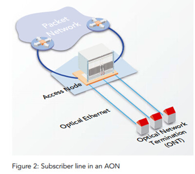
Comparison of the Technologies AON vs. PON
The key technical difference between active and passive access technology is that a passive splitter is used for passive optical networks. The splitter is basically a kind of multi-mirror that distributes the optical signal for the subscriber line to fiber optic routes without any electrical current. Besides, PON is efficient since each fiber optic strand can serve up to many users. On the other hand, because the bandwidth in PON is not dedicated to individuals, it is more difficult to figure out failures when disturbances of fibers occur. The share of fiber optic strands for portions of the network needs PON subscribers to be geographically closer to the central source of the data, likely that subscribers enjoy a slowdown data transmission with a distance limitation up to 20 km.
As for AON subscribers, the bandwidth in each port is dedicated to each individual without sharing of it. Thus, higher bandwidth per port is possible through AON network. In addition, because of its dedication to specific individual, it is easier to detect fiber faults or problems in case of AON. However, an AON system requires active equipment to manage signal transmission, which means power supply and potentially higher costs.
When deciding between a PON or an AON, it is important to consider what services are going to be delivered over the network, the overall network topology and who the primary customer will be. For example, radio frequency video services will be deployed, then a PON is typically the only practical solution. If all services are Internet Protocol-based, however, either a PON or an AON could be appropriate. If there are longer distances involved and providing power and cooling to active components in the field could pose a problem, then a PON may be the best choice. Alternatively, if the target customer is commercial or if the project involves multiple dwelling units, then an AON may be a better fit.
Conclusion
There is no one technology that can apply in all cases. Basically passive optical networks are a better choice for network operators who want to supply a very large number of subscribers. While the active optical technology is more suitable for private network operators, that either lay their own fiber optic lines. Besides these two network versions, EPON and GPON are popular versions of PONs. These short-haul networks of fiber-optical cable are used for Internet access, voice over Internet protocol (VoIP), and digital TV delivery in metropolitan areas. FS.COM is a top manufacturer for optical products, such as DAC Twinax cables (SFP+ Cables, XFP Cables, CX4 Cables, Infiniband Cables, etc) and optics transceivers, including (QSFP+, SFP, SFP+, XFP, X2, XENPAK, SDH, Bidi), OADM/MUX/Demux, Fiber Optic Patch Cords (LC-SC fiber cable) and Fiber Optic Components, etc.
Oznake: Pon, AON, FTTH, fiber cables, Passive Optical Networks, Active Optical Networks
komentiraj (0) * ispiši * #
