Learning Five Ways to Test Fiber Optic Cables
srijeda , 29.06.2016.In this technological world filled by fiber optic systems everywhere, one won’t fail to enjoy the benefits brought by fiber optics in daily life. In a whole fiber optic system, the most essential part should be the fiber optic cable. This cable is made up of incredibly thin strands of glass or plastic capped with the same (eg. ST ST fiber cable) or different connector types (LC ST patch cable) on the ends, used as the medium to carry information from one point to another with light-based technology. Just like electricity that can power many types of machines, beams of light can carry many types of information, so fiber optics do great to people in many ways, like broadcasting, transportation, medicine, etc..Along with the heavy use of fiber optic cables, testing the installed cables also gains importance in practical use. Since there are many standards available for testing, some people may get confused. But don’t worry. This text is written with an attempt to clear off this confusion.
Testing Principles
Generally speaking, five ways are listed in various international standards from the EIA/TIA and ISO/IEC to test installed cable plants. First three of them use test sources and power meters to make the measurement, while the last two use an optical time domain reflectometer (OTDR). Let’s first see the different results from these methods, and then delve into each one.

The use of source and power meter method, also known as “insertion loss”, simulates the way the actual network uses the cable plant. The test source mimics the transmitter, and the power meter the receiver. But insertion loss testing requires reference cables attached to the source and meter to connect to the cable under test. This insertion loss test can use 1, 2 or 3 reference cables to set the “zero dB loss” reference for testing. Each way of setting the reference gives a different loss. While OTDR is an indirect method, using backscattered light to imply the loss in the cable plant, which can have large deviations from insertion loss tests. OTDRs are more often used to verify splice loss or find damage to cables.
Source/Power Meter Method
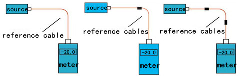
In source and power meter method, all the three tests share the same setup (shown below), but the reference power can be set with one, two or three cables as explained next. In general, the 1 reference cable loss method is preferred, but it requires that the test equipment uses the same fiber optic connector types as the cables under test. If the cable (ST ST fiber cable) has different connectors from the test equipment (SC-SC on the tester), it may be necessary to use a 2 or 3 cable reference, which will give a lower loss since connector loss is included in the reference and will be subtracted from the total loss measurement.

Reference per TIA OFSTP-14 (1 Cable Reference)
This method, formerly called method B, uses only one reference cable. The meter, which has a large area detector that measures all the light coming out of the fiber, effectively has no loss, and therefore measures the total light coming out of the launch reference cable. When the cable is tested as below, the measured loss will include the loss of the reference cable connection to the cable plant under test, the loss of the fiber and all the connections and splices in the cable plant and the loss of the connection to the reference cable attached to the meter.
Reference per TIA OFSTP-14 (2 Cable Reference)
This one, formerly called method A, uses two reference cables with one launch cable attached to the source, and the other receive one attached to the meter. (The two cables are mated to set the reference.) Setting the reference this way includes one connection loss (the mating of the two reference cables) in the reference value. When one separates the reference cables and attaches them to the cable under test, the dB loss measured will be less by the connection loss included in the reference setting step. This method gives a loss that's less than the 1 cable reference.
Reference per TIA OFSTP-14 (3 Cable Reference)
Reference cables are often patch cords with plugs, while the cable under test has jacks on either end. The only way to get a valid reference is to use a short and good cable as a "stand-in" for the cable to be tested to set the reference. To test a cable, replace the reference cable with the cable to test and make a relative measurement. Obviously this method includes two connection losses in setting the reference, so the measured loss will be less by the two connection losses and have greater uncertainty. Finally, here goes the picture showing the testing case with one, two, three reference cables.
OTDR Testing
With only one lunch cable, the OTDR can measure the length of the cable under test and the loss of the connection to the cable under test plus the loss of the fiber in the cable under test, and any other connections or splices in the cable under test. However, this method doesn’t test the connector on the far end of the cable under test, because it isn’t connected to another connector, and connection to a reference connector is necessary to make a connection loss measurement.

If a receive cable is used on the far end of the cable under test, the OTDR can measure the loss of both connectors on the cable under test as well as the fiber in the cable, and any other connections or splices in the cable under test. The placement of the B marker after the connection to the receive cable means some of the fiber in the receive cable will be included in the loss measured.
Conclusion
Hope this article is helpful for you to understand various methods existing to test fiber optic cables. For more information about testing methods or testing tools, you can directly connect me at Linkedin@Fern Xu (Fiberstore).
Oznake: fiber optic cable, LC ST patch cable, ST ST fiber cable, cable testing methods, source and power meter, OTDR
komentiraj (0) * ispiši * #
Introduction to 40G QSFP+ Cabling Assemblies
petak , 24.06.2016.Today’s high-performance computing environments featuring by switching and routing, cloud computing and virtualization require higher network speeds, greater scalability, and higher levels of performance and reliability in data centers. Some bandwidth-hungry applications, like video streaming applications, also drive data rates to higher points. These all boost the need for a migration to 40G and 100G interfaces as 1 and 10G can’t meet the bandwidth needs well. 40G interface is QSFP (Quad Small Form-factor Pluggable) which has several standards requiring different connectors to fit cabling infrastructure, so as to achieve network connectivity. Do you know what cabling infrastructure is needed to support 40G applications? MPO/MTP cable, direct attach cable (DAC), or LC fiber patch cable? Have any ideas? Follow this article and find the answer.
MTP/MPO Cable
MTP is a registered trademark of US Conec used to describe the connector, and MPO stands for multi-fiber push-on or also multi-path push-on. Actually, the former product is 100% compatible with the latter. Thus, only MTP is written for simplicity in the following paragraphs. In 2010, the IEEE 802.3ba standard specifies MTP connectors for standard-length multi-mode fiber (MMF) connectivity. Its small, high-density form factor makes MTP cable ideal for higher-speed 40G networks in data centers.
To support 40G applications, a 12-fiber MPO connector is needed. The typical implementations of MTP plug-and-play systems split a 12-fiber trunk into six channels that run up to 10 Gigabit Ethernet (depending on the length of the cable). 40G system uses 12-fiber trunk to create a Tx/Rx link, dedicating 4 fibers for 10G each of upstream transmit, and 4 fibers for 10G each of downstream receive, leaving the middle 4 fibers unused. The upgrade path for this type of system entails simply replacing the cassette with an MTP-to-MTP adapter module.
Direct Attach Cable
Besides MTP cable, many data centers also like to choose DACs for 40G cabling infrastructure. DAC, a kind of optical transceiver assembly, is a form of high speed cable with “transceivers” on either end used to connect switches to routers or servers. The “transceivers” on both ends of DACs are not real optics and their components are without optical lasers, thus DACs are much cheaper, preferable for 40G data center applications. As such, the fiber connectivity cost is significantly reduced by using either direct attach copper cables or active optical cables (AOCs) instead of costly fiber transceivers and optical cables.
Direct Attach Copper Cable
Direct attach copper cables are designed in either active or passive versions for short-reaches in data center. Compared with active optical cables, these copper cables are less expensive. Nowadays, there are many twinaxial cables available to support 40G (10G x four channels), in QSFP+ to QSFP+ (ie. EX-QSFP-40GE-DAC-50CM) version or in QSFP to 4 SFP+ cable assembly (eg. QSFP-4SFP10G-CU5M).

The issue is that copper cable is stiff and bulky, thus consuming precious rack space and blocking critical airflow. But with the advancing technology, manufactures produce a thinner, uniquely shielded ribbon-style twinaxial cable that can support speeds of 10G per channel while addressing many of the concerns associated with round, bundled cable. And the ribbon-style twinaxial cable is significantly slimmer than its round counterparts. Even better, the cable can be folded multiple times and still maintain signal integrity, allowing for higher density racks and space savings.
Active Optical Cable
Being a form of DAC, AOC integrates single-mode fiber (SMF) or MMF cable terminated with a connector and embedded with transceivers. It uses electrical-to-optical conversion on the cable ends to improve speed and distance performance of the cable. AOCs can reach a longer distance copper cables, and use the same interfaces as copper cables, typically used in data center. Similar to direct attach copper cables, AOCs are also available in QSFP+ to QSFP+ (eg. QSFP-4X10G-AOC20M) and QSFP+ to 4 SFP+ cabling (ie. QSFP-4X10G-AOC10M) versions.
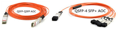
Since 40G AOC connectors are factory pre-terminated, 40G AOC is easier for installation and thus less affected by the repeating plug during daily use than MTP cable. In case there was a fault in the interconnection, for AOC, you can just replace it with another AOC.
LC Fiber Cable
Certainly, LC fiber cable can also be the cabling solution for the long-reach 40G QSFP+ modules (40GBASE-LR4). That is, 40GBASE-LR4 QSFP+ uses a duplex LC connector as the optical interface, able to support transmission distance up to 10km over single-mode fiber (SMF).
Conclusion
40G cabling assemblies, including MTP cable, DAC, AOCs, and LC fiber cable, permit multiple connectivity options in data centers. While for some companies, the main issues facing them are the the low-quality and incompatible products. If you choose Fiberstore for product, then such quality and compatibility problems can be avoided. Besides, its 40G cables are test-assured to be compatible with major brands, provided at really low prices. You can visit Fiberstore for 40G cables to achieve 40Gbit/s links.
Oznake: QSFP MTP cable LC fiber patch cable, DAC QSFP to 4 SFP+ cable AOC
komentiraj (0) * ispiši * #
Fiber Optics: Do You Know Its History & Advantages?
srijeda , 22.06.2016.As we all know that the medium is considered as the simplest form of fiber optics, which is used to carry information from one point to another in the form of light. It's comprised of a transmitter used to generate the light signal, a fiber optic cable that functions as a conduit for pulses of light to travel over distances,, and a receiver to accept the light signal transmitted. In practical use, fiber systems are often deployed as the alternative solutions to traditional copper-based communications systems, since fiber optic cables outperform copper cables in less signal loss and immunity to electromagnetic interference (EMI). Of course, the advantages of fiber optics are denifinely not confined to these two points. Read this article and the following detail the several strong points of fiber optics used in communication systems, as well as its history.
Fiber Optics: History
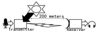
In 1880, the photophone was invented, a great inventory used to speak into a microphone which would then cause a mirror to vibrate. The sun's light would strike the mirror, and the vibration of the mirror would transmit light across an open distance of about 656ft (200m). The receiver's mirror would receive the light and cause a selenium crystal to vibrate, causing the noise to come out on the other end. Although the photophone was successful in allowing conversation over an open space, it had a few drawbacks: it did not work at night, in the rain or if someone walked between the signal and receiver. Then this idea was given up.
In 1950s, the laser was invented. This device was a finely controlled beam of light that could transmit information over long distances. Unfortunately, the same drawbacks also plagued the laser. Although it could be used at night, it did not work during rain, fog or at any time when a building was erected between the sender and the receiver.
Scientists at Corning developed the first practical fiber optic cables in the 1970s, based on the idea of "total internal reflection". This is the principle that fiber cables are built upon, and it basically means that an optical fiber consists of a core of transparent glass, surrounded by outer layer, (called "cladding") of slightly less transparent glass which reflects the light back into the core.
What Makes Fiber Optics Special?
What is special about fiber optics? As mentioned above, fiber optic cables are made out of glass, and carry pulses of light energy. The idea of a flexible piece of glass sounds a bit counter-intuitive, but in some ways, fiber optic cables are stronger and more durable than copper cables.
Nowadays, fiber optic cables are used for many different telecommunication applications, like data centers, data warehouses, server farms, SANs, and LANs. But actually, in their practical use, there exists a common question. One may find himself faced single-mode fibers (SMFs) and multi-mode fibers (MMFs) which are terminated with different connectors, such as LC (LC fiber cable), SC (LC to SC cable), MTP/MPO (MTP cable). When such things occur, it’s important to keep in mind that SMFs and MMFs are not compatible with each other, and can't mix them together between two end points.

Fiber Optics: Advantages
Why is fiber optics used in telecommunications? There are several reasons that make fiber systems more popular than copper ones.
Large Bandwidth & Long Distance
Bandwidth refers to the amount of data that can be passed along a cable in a given time period. If we think of cables as pipes, then bandwidth is the amount of water that can flow through the pipe in a second. The bigger the pipe, the more water can flow. Consider a normal communication cable that may be used to carry a single phone call. It is built out of copper, and may have the bandwidth of a normal drinking straw. By comparison, a fiber cable of the same physical size would provide more bandwidth.
Since fiber optic signal is made of light, very little signal loss occurs during transmission, and data can move at higher speeds and greater distances. In most cases, copper cables are limited to a range of 100meters or less. In contrast, the relatively small diameter and light weight of fiber optic cables can allow a wide range of distance reaches from 550meters to dozens of kilometers, which makes fiber ideal for applications where signals have to travel over long distances.
Immunity & Reliability
Fiber optics provides extremely reliable data transmission. It’s completely immune to many environmental factors that affect copper cable. The core is made of glass, which is an insulator, so no electric current can flow through. It’s immune to electrometric interference and radio-frequency interference (EMI/RFI), crosstalk, impedance problems, and more. You can run fiber optic cable next to industrial equipment without worry. Fiber is also less susceptible to temperature fluctuations than copper and can be submerged in water.
Security
The data is safe with fiber cable which doesn’t radiate signals, letting information difficult to be tapped. More specifically, the dielectric nature of fiber optic cable makes it impossible to remotely detect the signal being transmitted within the cable. If the cable is tapped, it’s very easy to monitor because the cable leaks light, causing the entire system to fail. If an attempt is made to break the physical security of your fiber system, you’ll know it. Fiber networks also enable you to put all your electronics and hardware in one central location, instead of having wiring closets with equipment throughout the building. They are very attractive for use in governmental institutions, finance/banking and other environments with major security concerns.
Summary
It's obvious that fiber optics has a growing usage in both private and public networks. It's able to transmit signals over significantly distance at high speed and large amount, extremely suitable for voice and data links. As an outstanding fiber patch cord manufacturer, Fiberstore provides various kinds of fiber optic cables terminated with the same or hybrid connectors on the ends to cover countless applications, including the above mentioend LC fiber cable, LC to SC cable, MTP cables, and so on. They are all supplied at cost-effective prices. Really worth your try.
Oznake: fiber optic cables, LC to SC cable, LC fiber cable, SMFs, MMFs, fiber patch cord manufacturer
komentiraj (0) * ispiši * #
A Rundown of Fiber Optic Connectors
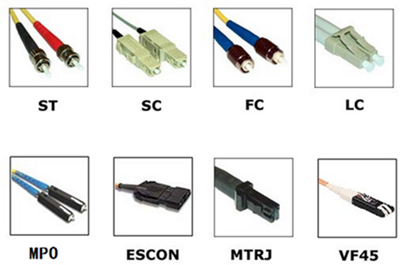
petak , 17.06.2016.During the rapid development of fiber optic technologies over the past decades, fiber product manufacturers and companies have released countless sophisticated equipment, during which the so-called “better mousetrap”—fiber optic connectors attract users’ attention. These smart connectors are used to terminate at the ends of fiber optic cables to form fiber optic jumper, like fiber cable LC to LC. Since a variety of splice options are available to fiber network planners today, connector types are diversified, eg. ST, SC, LC, MTP/MPO connectors. Each connector has its own unique design and therefore, pros and cons. Then question occurs, how to choose the suitable ones that are lower loss, lower cost, easier to terminate or to solve some other perceived problems? Have some ideas? If not, don’t worry. Here is a rundown of several leading connector types, introducing their strengths and weaknesses respectively.
Fiber Optic Connector Design
Most fiber optic connectors are known to be pluggable male connectors with a protruding ferrule that holds the fiber optic cables and aligns them for mating. They use a mating adapter to mate the two connector ferrules that fit the securing mechanism of the connectors (bayonet, screw-on or snap-in.). The ferrule design is also useful as it can be used to connect directly to active devices like LEDs, VCSELs and detectors. Image below helps you to get the idea of different connector sizes.
Fiber Optic Connector Color Codes
In earlier ages, single-mdoe connectors are always in yellow, while multi-mode ones in orange, black or gray. But the advent of such metallic connectors as FC and ST made color coding difficult, so colored boots were often used. The TIA 568 color code for connector bodies and/or boots is Beige for multi-mode fiber (MMF), and Blue for single-mode fiber (SMF), and Green for APC (angled) connectors.
Fiber Optic Connector Types
Table listed below shows differences among several most common fiber optic connectors.
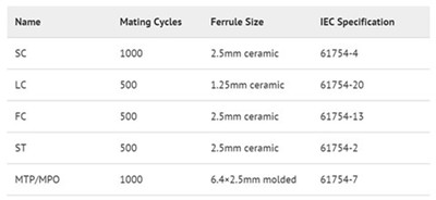
SC Connector
SC, sometimes referred to as square connector, was developed by the laboratories at Nippon Telegraph and Telephone (NTT) in the mid-eighties. Standardized in TIA-568-A, the SC has a push-pull coupling end face with a spring loaded 2.5mm ceramic ferrule. At first, SC was not widely used because of its high cost, but with manufacturing costs coming down, it slowly grew in popularity in datacoms and telecoms applications including point to point and passive optical networking.
LC Connector
LC connector, licensed by Lucent Technologies, is a small form factor connector that utilizes a latch as opposed to the SC locking tab, and with a 1.25mm ferrule, half the size of the SC. It’s just because of its smaller size, LC becomes increasingly popular in datacoms and other high-density patch applications, as its combination of small size and latch feature make it ideal for densely populated racks/panels. With the introduction of LC compatible transceivers (say SFP-10G-SR) and other networking components, its steady growth in the communication arena is likely to continue.
FC Connector
Different to the plastic bodied SC and LC, FC uses a round screw-type fitment made from nickel-plated or stainless steel. The connector end face relies on an alignment key for correct insertion and is then tightened into the adaptor/jack using a threaded collet. Despite the additional complexity both in manufacturing and installation, it’s still the connector choice for precise measuring equipment such as OTDRs.
ST Connector
ST was developed by AT&T. Judging from appearance, ST and FC are almost the same, except that ST uses a bayonet fitment rather than a screw thread. The introduction of SC and LC has reduced the usage of ST and FC, since SC and LC deliver similar performance to ST and FC, but both have less expensive components and are quicker to connect. Additionally, ST cannot be terminated with an angled polish, which limits use in SMF and FTTH applications.
MTP/MPO connector
Just like SC, MT ferrule connector is also NTT’s invention coming in the 1980s. But this technology has only recently become popular under branded versions of the multiple fiber push-on/pull-off connector, such as MTP and MPO. It is larger than the other connectors but for good reason - it can support up to 24 fibers in a single ferrule. They are extensively used in high density patch environments such as data centers they are used extensively, both at single mode and multi-mode wavelengths.
It’s known that the sequence of the fibers cannot physically be changed after termination, so MTP/MPO connector is supplied with a fan-out assembly at the opposing end, such as LC. This allows the operator to change channels simply by re-patching the fanned-out side of the cable.
Conclusion
After description, it’s easy to identify these connectors and choose the right ones for your networking use according to their design and usage. Fiberstore supplies various kinds of connectors with high quality and at low prices. Besides, connector compatible fiber patch cords are also available, including fiber cable LC to LC mentioned above, SC SC fiber cable, ST ST fiber cable, and so on. You can visit Fiberstore to know more information about fiber optic connectors and their compatible fiber cables.
Oznake: fiber optic connectors, SC, LC, FC, st, MTP/MPO, fiber cable LC to LC, SC SC fiber cable
komentiraj (0) * ispiši * #
Comparison Among Twisted Pair, Co-axial Cable and Fiber Optics
srijeda , 15.06.2016.In communication systems, massive bundles of wires and cables are used to transport data between servers and other equipment. These cables can be twisted pair cables, co-axial cables and fiber optic cables. Since all these three types can be applied to network communications, it’s essential to determine which cable type is the best for the reliable and efficient data transfer, meaning that a basic understanding of their respective designs and features is necessary. This text aims to compare these three kinds and discuss the differences among them.
Twisted Pair Cable
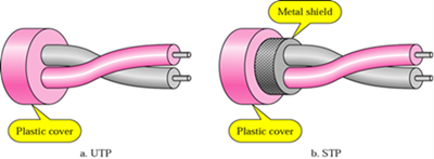
Twisted pair cable is a kind of wiring in which two conductors of a single circuit are twisted together, with one conductor serving as the forward circuit and the other as the return circuit. The twisted cabling design helps to reduce noise from outside sources and crosstalk on multi-pair cables, making it suitable for use in the field of telecommunication for a long time.
Twisted pair cable comes in two versions (image shown below): unshielded twisted-pair (UTP) and shielded twisted-pair (STP). Since UTP cable lacks shielding, it’s more susceptible to interference from electronic devices. Or in another way, STP cable consists of a foil jacket which helps to prevent crosstalk and noise from outside source. STP is commonly used in Token Ring networks and UTP is in Ethernet networks.
Co-axial Cable
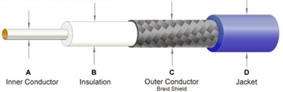
Co-axial cable, or sometimes referred to as coax, is a type of cable that has four layers. That is, at the core is an inner conductor which is surrounded by a foam insulation, symmetrically surrounded by a woven braided metal shield, then covered in a plastic jacket (just as the following picture shows). Because of its insulating property, coaxial cable can carry analogy signals with a wide range of frequencies. It’s seldom used in computer networks anymore, but widely used in cable television services and video connections, like those used by closed circuit surveillance systems.
There are two coaxial cables: 75 Ohm and 50 Ohm. The former is primarily used to transmit a video signal, like television signals over cable. While the main application of the latter is transmission of a data signal in a two-way communication system. Other typical applications include computer Ethernet backbones, wireless antenna feed cables, GPS (Global Positioning Satellite) antenna feed cables and cell phone systems.
Fiber Optic Cable
Fiber optic cable is the complete assembly of fibers, and uses light pulses to transmit information down fiber lines instead of using electronic pulses to transmit information down copper lines. Each of the optical fiber elements is individually coated by plastic layers and contained in a protective tube. A fiber optic cable can accommodate many wavelengths (or channels), able to accommodate ever-increasing data capacity requirements. When terminated with LC/SC/ST/FC/MTRJ/MU/SMA connectors on both ends, such as LC-LC, LC-ST, SC-SC, ST-ST, LC SC cable, fiber optic cables can achieve fiber link connection between equipment during fiber cabling.

Comparison Among Three Cables
Before delving into comparison between these three cables, a table about their respective strengths and weaknesses is available.
Comparing Twisted Pair & Co-axial Cable
Both twisted pair and co-axial cable can support network speeds in both the megabit and gigabit ranges. Both are susceptible in varying degrees to signal interference, as well as signal leakage. (Signal interference occurs when external signals interfere with transmission inside the cable, and signal leakage means that signals inside the cable leak out and become a source of interference to other devices.) Coaxial cable, being of a standard design, varies little in its susceptibility to interference. For twisted pair cable, however, the cable’s resistance to interference depends in large part on the degree to which the twisting scheme remains in place, and therefore can vary widely.
Comparing Twisted Pair & Fiber Optic Cable
Judging from cable and installation costs to tooling and transceivers, twisted pair, here mainly refers to UTP, is much less costly than fiber optic cable. The one obvious difference lies in the quality. Passive to active UTP systems offer performance similar to fiber, providing noise immunity, attenuation compensation, surge protection and ground loop isolation. Because of this point, those users, who once deployed fiber optic cables for runs beyond the range of co-axial cable, now choose UTP for transmission. Fiber optic cable is good for extremely long runs (over one mile) or for safety when video is run in the same conduit with high voltage.
Allowing for distance, if cable runs less than 250 feet, co-axial cable is probably the best option. Between 250 and 8,000 feet, UTP wire is often the best one. If the runs are more than 8,000 feet, it’s advised to select fiber optic cable.
Conclusion
While deciding whether to use co-axial cable, twisted-pair, or fiber optic cable for transmission, it’s imperative to collect the basic information about them, and take the cost, cable runs and other external conditions into consideration. In Fiberstore, you can find different types of UTP cable (eg. Cat 5, Cat5e, Cat6) and various fiber optic cables (say LC SC cable mentioned above, SC to SC fiber patch cable). You can go to Fiberstore to know more information about both copper and fiber optic cables.
Oznake: twisted pair, co-axial cables, UTP, STP, fiber optic cables, LC SC cable, SC to SC fiber patch cable
komentiraj (0) * ispiši * #
Fan-out Technology Used in 40GbE Deployment
srijeda , 08.06.2016.Obvious is the growing need for bandwidth required to accommodate various cloud services, smooth multimedia downloads or uploads, video streaming, as well as growing wireless usage. 10Gbps links are not sufficient enough to handle the increased bandwidth. As such, it’s imperative to deploy Higher Speed Ethernet (HSE) network, say 40GbE, by using devices that scale to match customer demands. Besides adding more devices and cables, higher port density is also the ideal solution to get greater bandwidth. To deliver the higher HSE port density for 40GbE interfaces, fan-out (breakout or harness) cabling technology is introduced here which also meets the need to keep costs at a manageable level.
Fan-out Technology Basics
Being one of the latest enabling technologies to help increase port densities and lower costs, fan-out technology is easy to be grasped. At first sight, a fan-out cable looks very simple. It takes one (large bandwidth) physical interface and breaks it out into several (smaller bandwidth) interfaces. A typical example of this is QSFP to SFP+ cable assembly which takes one 40G QSFP interface on one end and uses a fan-out cable to break it into four SFP+ interfaces one the other end. In this QSFP+ assembly, a fan-out cable enables splitting out the 4 lanes into Tx/Tx pairs usable for 10GE transmissions.
However, the truth is not definitely just as its face. This complex fan-out technology is critically important in the distribution layer of 40G data center. The following passages discuss two fan-out assemblies that are widely used in 40G data center.
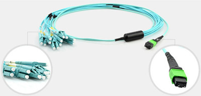
40G MPO/MTP Fan-out Cables
Here goes to the MPO/MTP fan-out cables in 40GbE transmission firstly. A MPO/MTP fanout cable is a multi-fiber optical cable that contains several individual tight buffered optical fibers with one end terminated with a male/female MPO connector and the other end usually terminated with several LC connectors. Existing 40Gbps transmission over this multi-mode backbones is accomplished by using an LC to MPO fan-out assembly to connect the existing LC connectors in the installed cabling to the MPO connector in the 40Gbps.
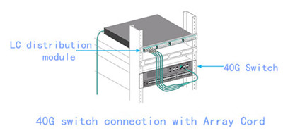
There are many MPO fan-out cable types. For 40G cabling, the most common breakout cable type is the one which is able to fan out into 12 fibers. (a typical 12-fiber MPO breakout cable often with OM3 optical fiber as the transmission media is shown below). This 12-fiber MPO fan-out cable is terminated with 6 duplex LC connectors on one end and a male MPO connector on the other end, which can work from MPO trunk backbone assemblies to LC fiber rack system in high density backbone cabling from 40G device to 10G devices.
40G Direct Attach Fan-out Cables
Direct attach cable (DAC), as a kind of optical transceiver assembly, is also available in fan-out design. It’s a form of high speed cable with “transceivers” on either end used to connect switches to routers or servers. Although the “transceivers” on both ends of DACs are not real optics and their components are without optical lasers, they perform the similar functions as the real transceivers. DAC fan-out cables can be divided into direct attach copper breakout cables and active optic fan-out cables.
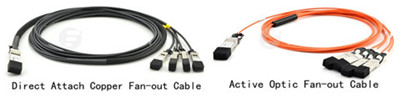
Converting one form factor to a different form factor is necessary in many cases. For example, a 40G device may be connected to one or several 10G devices for distribution or adapting. With fan-out DAC, this process would be much easier. This pre-terminated components can also increase the reliability of data center effectively.
Fan-out Technology Consideration
One important consideration for fan-out technology is that for each group of fan-out ports, there must also be a MAC (media access control) engine and the entire IEEE reconciliation layers behind it. For example, a 40GE QSFP port in fan-out to 4x10GE links must have four individual 10GE MACs running behind each group of electrical lanes. The port electronics must be able to switch from a single 40GbE MAC to 4 10GbE MACs, and back again to a single 40GE MAC. This process is integral in assuring that the lanes have a correct and trackable MAC assignment -- it is crucial to make fan-out technology actually work.
Conclusion
40G fan-out technology separates a single physical interface into multiple physical interfaces that are 410GbE-capable, providing high-density interfaces over multiple speeds. This increases interface flexibility at lower costs. Fiberstore offers a wide selection of fan-out MPO and DAC cables (QSFP to SFP+ cable) for your 40G transmission. Besides these 40G cables, 40G modules which are fully compatible with major brands can also be found, such as Cisco QSFP-40G-SR-BD. This compatible module just costs you US$ 300.00 at Fiberstore, but when you search it on Amazon or somewhere else, it seems that you have to pay more than US$ 400.00 for a new one.
Oznake: 40GbE, fan-out cable, QSFP to SFP+ cable, MPO/MTP fan-out cables, DAC fan-out cables, 40G QSFP, Cisco QSFP-40G-SR-BD
komentiraj (0) * ispiši * #
High-density MPO/MTP Cabling Assemblies in Data Centers
petak , 03.06.2016.Along with the advent and heavy use of big data and cloud computing, the demand for high-speed transmission and great data capacity is growing more vigorously than ever before in this fast-changing mobile world. A large number of servers are housed in cloud-computing data centers of some big enterprises and organizations. Thus, today’s data centers are faced with such a major challenge: how to obtain the balance of high -capacity & -transmission data rate and low power consumption. As data throughput increases, 40/100Gbps are more common and now become a trend and hot-spot for data-center cabling system, with the MPO/MTP connector being the popular optical interface for 40/100GbE network. This article is aimed at introducing high-density MPO/MTP cabling assemblies in data centers.
MPO/MTP Cable Benefits
MPO/MTP cable, a significant part of structured cabling, is designed for the reliable and quick operations in Data Centers. The obvious benefits of these cables are less space occupation and improved scalability, providing significant space and cost savings, widely used in 40GbE and 100GbE network environment. MPO/MTP cabling assemblies include patch cables, trunk cables, harness (fan-out or breakout) cables, cassettes, etc..
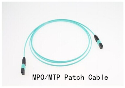
MPO/MTP Patch Cables
MPO/MTP patch cables come into use when 40G or 100G transceivers are employed with MTP/MPO interface, say QSFP+ module (ie. 40G-QSFP-SR4) or QSFP28 optics (ie. JNP-QSFP-100G-SR4). The ends of MTP/MPO fiber cables are terminated with the customer's choice of 12-fiber or 24-fiber MPO connectors. Available in a male-to-male version (left with guide pins) and a female-to-female version (without pins), these cables are used in various applications such as all-optical networking and devices like the above-mentioned 40G/100G optics.
MPO/MTP Trunk Cables
MPO/MTP trunk cables function as a permanent link that connects MPO/MTP modules to each other. Available with 12, 24, 48 and 72 fibers, these cables are used to facilitate rapid deployment of high density backbone cabling in data centers and other high fiber environments reducing network installation or reconfiguration. A 72-fiber MPO/MTP trunk cable can be terminated with 6 MPO/MTP connectors which are manufactured specifically for multi-fiber loose tube or ribbon cable.
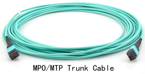
These cables can interconnect cassettes, panels or ruggedized MPO fan-outs, allowing for the flexibility in case any decision is made to change the connector style in the patch panels, new cassettes can be installed with the new connector style on the cross-connect side of the patch panel without having to change the connector on the cable trunk.
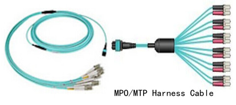
MPO/MTP Harness Cable
MPO/MTP harness cables provide a transition from multi-fiber cables to individual fibers or duplex connectors. They are suitable for many device needs like 100G modules, including CFP, CFP2 and CFP4 series. It provides a reliable, cost-effective cabling system for migrating from legacy 10G to higher speed 40G/100GbE. For instance, 12-fiber MPO to 4 duplex LC can be used to connect four 10G SFP+ (SFP-10G-SR) with one 40G QSFP+ (40G-QSFP-SR4).
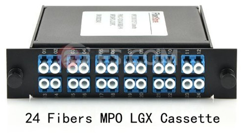
MPO/MTP Cassette Modules
MPO/MTP cassette modules permit rapid deployment of high density data center infrastructure as well as improved troubleshooting and reconfiguration during moves, adds and changes. They enable users to take the fibers brought by a trunk cable and distribute them to a duplex cable. As already assembled units, the MPO cassette modules are fitted with 12 or 24 fibers and have LC, or SC adapters on the front side and MPO/MTP at the rear, this is to say, inside a standard LGX cassette module, there is a hydra cable.
MPO/MTP Cable Heavy Use
Now many big companies are replacing their existing infrastructure with MPO/MTP cassettes in their patch panels to route data for thousands of network electronics, all making MPO/MTP cassettes, patch-cords, connectors and adapters an essential backbone to their infrastructure. If you run one 12-fiber MPO/MTP cable from a cassette on one side of the building to one cassette on the other, you can supply data for 12 connections just like that. The high fiber count in one connector creates endless possibilities. By deploying these different types of MPO/MTP cable in different locations of a data center, there occur several solutions for structured cabling systems that are key to data centers.
Conclusion
MPO/MTP cables come as the solver to meet the demanding request for higher network capacity as data expenses than expected. Fiberstore, as a professional fiber optic product supplier, offers various high-density MPO/MTP cables, trunk and harness versions, patch cords, and cassette module all included. Besides MPO/MTP cables, other cables are also supplied, like LC ST patch cable, LC SC cable, SC SC fiber cable, and so on. You can visit Fiberstore for more information about numerous amounts of cabling assemblies.
Oznake: MPO/MTP cable, MPO/MTP patch cables, MPO/MTP trunk cables, MPO/MTP harness cables, MPO/MTP cassette modules, LC ST patch cable
komentiraj (0) * ispiši * #
Proper Management of Fiber Patch Cord
srijeda , 01.06.2016.Past several years has witnessed a rapid deployment of fiber optic patch cables in optical communication networks. Compared with electrical cables, fiber patch cords (or called fiber optic jumper) are designed with enormous bandwidth capabilities, which make them preferred in digital and analog data transmission. These jumpers are fiber optic cables that are terminated at each end with connectors that plug into various pieces of equipment, available in single-mode and multi-mode patch cord versions (with OM3 patch cable widely used for short-reach transmission).
As fiber optic technology develops, the installation of fiber patch cords becomes increasingly easy nowadays. But to guarantee smooth networking performance, the proper patch cable management is essential. With proper management, it’s simple to go on cable operation and maintenance, saving time and cost. This article mainly discusses five factors that need to be considered during patch cord management.

Kinks, snags, pinches and poor contacts can dramatically reduce the performance of a fiber patch cord. The following factors are important in avoiding these problems.
Bend Radius
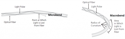
Since fiber optic cable made of glass has a fragile core, it requires great care and attention to avoid breaking this core during cable termination and operation. And in no case is fiber’s bend radius allowed. The minimum bend radius for patch cords varies with cord diameter. For 1.6mm and 3.0mm cords, the minimum un-loaded bend radius is 1.4 in (3.5cm), and for InstaPATCH Plus MPO patch cords, the minimum bend radius is ten times the cord diameter. If a fiber cable is bent excessively, the optical signal within the cable may refract and escape through the fiber cladding which will cause a loss of signal strength and is known as bend loss.
In addition, bending, especially during the installation and pulling of fiber patch cable might also cause micro cracks, and damage the fiber permanently. Generally, there are two basic types of bends in fiber, which are microbends and macrobends, with the latter larger than the former (as is shown below).
Patch Cord Path
This factor is closely related to the bend radius. The patch cable path should be clearly defined and easy to follow. Improper cable routing can lead to increased congestion in the termination panel, increasing the possibility of bend radius violations and possible failure in long-term. However, the well managed patch cable path ensures that bend radius requirements are maintained at all points, making accessing individual patch cable easier, quicker and safer. If the existing cord is the right length, it may be possible to re-use it. If this is the case, remove the cord completely and re-run it in through the cable pathways. This is the only sure way to ensure there are no tangles, kinks or strains in the cord.
Patch Cord Pulling & Stress
It’s not advised to use excessive force during the patching process, since too much force can stress cords and connectors, degrading their performance. If you need to use force in pulling a cord and there is something wrong, then stop and find the problem, and fix it before proceeding.
Patch Cord Accessibility
If the installed patch cable is easy to be accessed, the maintenance and operation would be quick without inducing a macrobend on an adjacent fiber. Accessibility is critical during network reconfiguration operations and directly impacts operation costs and network reliability.
Physical Protection
Patch cords that are routed between pieces of equipment can largely affect network reliability. Without proper protection, they would be easy to be damaged by technicians and equipment accidentally. Thus, physical protection of the installed patch cords is very important.
After discussing patch cord management, hers is another notice. Patching patch cord is critical in the first time, since its mistakes may cause disruption. Thus, after managing patch cord, taking time to make a final visual check on connections is a good investment. When patch panels are mounted in enclosures, ensure these are securely closed and, where necessary, locked, making sure that cord slack is not snagged or pinched by the doors.
Conclusion
Proper management of fiber patch cord can help to decrease operating costs and the time required to turn-up or restore service, making the operation reliable and flexible. As a professional fiber patch cord manufacturer, Fiberstore Cable Management provides ideal solutions for the distribution of cables and access to power, data and communication services on the wall and under the floor and for pole. Keep in mind those above-mentioned five factors, then the proper cable management is halt-succeeded.
Oznake: fiber optic patch cables, fiber optic jumper, OM3 patch cable, fiber patch cord manufacturer, cable management
komentiraj (0) * ispiši * #
