Fiber Optic Termination Overview
srijeda , 13.07.2016.It’s known that fiber optic termination methods vary based on the types of fiber optic cable being terminated, the style of connectors or splices used and the termination process appropriate for that connector. Generally speaking, fiber optic cable can be terminated in two ways—connectors that mate two fibers to create a temporary joint and/or connect the fiber to network equipment, and splices which create a permanent joint between the two fibers. Each termination method must have two primary characteristics: good optical performance (low loss and minimal reflectance) and high mechanical strength. As such, the terminations can be made in the right style, installed in a manner that provides low light loss and back reflection and protected against the expected environment, dirt or damage while in use. This passage mainly talks about the first method: connector.
Most fiber optic connectors are plugs or so-called male connectors with a protruding ferrule that holds the fibers and aligns two fibers for mating. Choosing a connector type for any installation should consider if the connector is compatible with the systems planned to utilize the fiber optic cable plant, if the termination process is familiar to the installer and if the connector is acceptable to the customer. If the systems are not yet specified, patch cords with different connectors on each end (e.g. LC ST patch cable) may be necessary.
Choice of Fiber Optic Connector
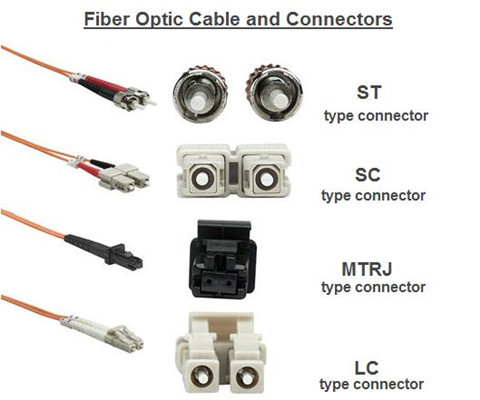
Fiber optic connectors are manufactured in different styles (say, ST, SC, LC, MT-RJ) that attach to the fibers in a fiber optic cable (LC to LC fiber cable single mode) by a number of methods, such as epoxy polish, prepolished/splice, etc.. ST is one of the most popular connectors for multimode networks, like most buildings and campuses. SC is a snap-in connector that is widely used in singlemode systems for it's excellent performance and multimode systems because it was the first connector chosen as the standard connector for TIA-568. LC uses a 1.25 mm ferrule, half the size of the ST. Otherwise, it's a standard ceramic ferrule connector, easily terminated with any adhesive. MT-RJ is a duplex connector with both fibers in a single polymer ferrule. It uses pins for alignment and has male and female versions, basically obsolete nowadays.
Termination Methods
Several termination methods are available for fiber optic cables, and the following passages list three terminations: adhesive termination, crimp/polish termination and prepolished termination.
Adhesive Termination
Epoxy Polish: The fiber is glued into the connector with two-part epoxy and the end polished with special polishing film. This method provides the most reliable connection and lowest losses. The epoxy can be allowed to set overnight or cured in a special oven. A “heat gun” should not be used to cure the epoxy as the uneven heat may not cure all the epoxy or may overheat it which will prevent curing.
Hot Melt: This connector is similar to the epoxy/polish connector but already has the adhesive (a heat set glue) inside the connector. The adhesive is liquefied in an oven before the fiber can be inserted. The fiber is secured when the adhesive cools.
Anaerobic Adhesives: These connectors use a quick-setting adhesive instead of the epoxy. They may use a single part adhesive or an adhesive and set- ting agent. Some adhesives do not have the wide temperature range of epoxies, so they should only be used indoors unless otherwise specified.
Crimp/Polish Termination
These connectors use a crimp on the fiber to hold it in the connector ferrule. The fiber can be polished like an adhesive connector or cleaved with a special tool. Insure the crimp is made properly to prevent fiber pistoning (pulling back or pushing forward in the connector ferrule.)
Prepolished Termination
These connectors have a short stub of fiber already epoxied into the ferrule and polished. Termination requires cleaving a fiber, inserting it into the back of the connector like a splice and crimping. The loss of these connectors will generally be higher than adhesive connectors, since they include the connector loss plus a splice loss in every connector.
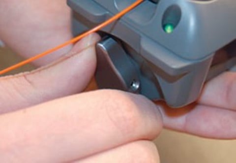
To ensure low loss, the fiber must be cleaved properly, which requires a good cleaver and good technique. Insure the crimp is made properly to prevent fiber pistoning. The termination process can be monitored with a visual fault locator.
Termination Process
Connectors can be installed directly on most cable types, including jacketed tight buffer types like simplex, zipcord and breakout cables, where the where the aramid fiber strength members in the cable are crimped or glued to the connector body to create a strong connector. Connectors can be attached to the 900 micron buffered fibers in distribution cables, but the termination is not as rugged as those made to jacketed cables, so they should be placed in patch panels or boxes for protection. The 250 micron buffered fibers in loose tube cables cannot be easily terminated unless they have a reinforcement called a breakout kit or furcation kit installed, where each fiber is covered by a larger plastic tube. Generally loose tube and ribbon cables are terminated by splicing on a terminated pigtail.
Cables can be pulled with connectors already on them if, and a big if, you can deal with two issues: First, the length must be precise. Too short and you have to pull another longer one (it’s not cost effective to splice), too long and you waste money and have to store the extra cable length. Secondly, the connectors must be protected. Some cable and connector manufacturers offer protective sleeves to cover the connectors, but you must still be much more careful in pulling cables. You might consider terminating one end and pulling the unterminated end to not risk the connectors.
When special tools are required, use them in the appropriate manner. And once installation is completed, connectors should be covered with an appropriate dust cap and stored in a safe location awaiting testing or connection to net- work equipment.
Conclusion
Fiber terminations must also be of the right style to be compatible to the equipment involved and be protected against the environment in which they are installed. When several connector types are all acceptable, or only one connector type is available but not ideal for the installation, the installer should discuss the merits of other types before committing to the project.
Oznake: fiber optic termination, fiber optic cable, connectors, LC ST patch cable, LC to LC fiber cable single mode
komentiraj (0) * ispiši * #
Learning Five Ways to Test Fiber Optic Cables
srijeda , 29.06.2016.In this technological world filled by fiber optic systems everywhere, one won’t fail to enjoy the benefits brought by fiber optics in daily life. In a whole fiber optic system, the most essential part should be the fiber optic cable. This cable is made up of incredibly thin strands of glass or plastic capped with the same (eg. ST ST fiber cable) or different connector types (LC ST patch cable) on the ends, used as the medium to carry information from one point to another with light-based technology. Just like electricity that can power many types of machines, beams of light can carry many types of information, so fiber optics do great to people in many ways, like broadcasting, transportation, medicine, etc..Along with the heavy use of fiber optic cables, testing the installed cables also gains importance in practical use. Since there are many standards available for testing, some people may get confused. But don’t worry. This text is written with an attempt to clear off this confusion.
Testing Principles
Generally speaking, five ways are listed in various international standards from the EIA/TIA and ISO/IEC to test installed cable plants. First three of them use test sources and power meters to make the measurement, while the last two use an optical time domain reflectometer (OTDR). Let’s first see the different results from these methods, and then delve into each one.

The use of source and power meter method, also known as “insertion loss”, simulates the way the actual network uses the cable plant. The test source mimics the transmitter, and the power meter the receiver. But insertion loss testing requires reference cables attached to the source and meter to connect to the cable under test. This insertion loss test can use 1, 2 or 3 reference cables to set the “zero dB loss” reference for testing. Each way of setting the reference gives a different loss. While OTDR is an indirect method, using backscattered light to imply the loss in the cable plant, which can have large deviations from insertion loss tests. OTDRs are more often used to verify splice loss or find damage to cables.
Source/Power Meter Method
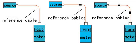
In source and power meter method, all the three tests share the same setup (shown below), but the reference power can be set with one, two or three cables as explained next. In general, the 1 reference cable loss method is preferred, but it requires that the test equipment uses the same fiber optic connector types as the cables under test. If the cable (ST ST fiber cable) has different connectors from the test equipment (SC-SC on the tester), it may be necessary to use a 2 or 3 cable reference, which will give a lower loss since connector loss is included in the reference and will be subtracted from the total loss measurement.

Reference per TIA OFSTP-14 (1 Cable Reference)
This method, formerly called method B, uses only one reference cable. The meter, which has a large area detector that measures all the light coming out of the fiber, effectively has no loss, and therefore measures the total light coming out of the launch reference cable. When the cable is tested as below, the measured loss will include the loss of the reference cable connection to the cable plant under test, the loss of the fiber and all the connections and splices in the cable plant and the loss of the connection to the reference cable attached to the meter.
Reference per TIA OFSTP-14 (2 Cable Reference)
This one, formerly called method A, uses two reference cables with one launch cable attached to the source, and the other receive one attached to the meter. (The two cables are mated to set the reference.) Setting the reference this way includes one connection loss (the mating of the two reference cables) in the reference value. When one separates the reference cables and attaches them to the cable under test, the dB loss measured will be less by the connection loss included in the reference setting step. This method gives a loss that's less than the 1 cable reference.
Reference per TIA OFSTP-14 (3 Cable Reference)
Reference cables are often patch cords with plugs, while the cable under test has jacks on either end. The only way to get a valid reference is to use a short and good cable as a "stand-in" for the cable to be tested to set the reference. To test a cable, replace the reference cable with the cable to test and make a relative measurement. Obviously this method includes two connection losses in setting the reference, so the measured loss will be less by the two connection losses and have greater uncertainty. Finally, here goes the picture showing the testing case with one, two, three reference cables.
OTDR Testing
With only one lunch cable, the OTDR can measure the length of the cable under test and the loss of the connection to the cable under test plus the loss of the fiber in the cable under test, and any other connections or splices in the cable under test. However, this method doesn’t test the connector on the far end of the cable under test, because it isn’t connected to another connector, and connection to a reference connector is necessary to make a connection loss measurement.

If a receive cable is used on the far end of the cable under test, the OTDR can measure the loss of both connectors on the cable under test as well as the fiber in the cable, and any other connections or splices in the cable under test. The placement of the B marker after the connection to the receive cable means some of the fiber in the receive cable will be included in the loss measured.
Conclusion
Hope this article is helpful for you to understand various methods existing to test fiber optic cables. For more information about testing methods or testing tools, you can directly connect me at Linkedin@Fern Xu (Fiberstore).
Oznake: fiber optic cable, LC ST patch cable, ST ST fiber cable, cable testing methods, source and power meter, OTDR
komentiraj (0) * ispiši * #
High-density MPO/MTP Cabling Assemblies in Data Centers
petak , 03.06.2016.Along with the advent and heavy use of big data and cloud computing, the demand for high-speed transmission and great data capacity is growing more vigorously than ever before in this fast-changing mobile world. A large number of servers are housed in cloud-computing data centers of some big enterprises and organizations. Thus, today’s data centers are faced with such a major challenge: how to obtain the balance of high -capacity & -transmission data rate and low power consumption. As data throughput increases, 40/100Gbps are more common and now become a trend and hot-spot for data-center cabling system, with the MPO/MTP connector being the popular optical interface for 40/100GbE network. This article is aimed at introducing high-density MPO/MTP cabling assemblies in data centers.
MPO/MTP Cable Benefits
MPO/MTP cable, a significant part of structured cabling, is designed for the reliable and quick operations in Data Centers. The obvious benefits of these cables are less space occupation and improved scalability, providing significant space and cost savings, widely used in 40GbE and 100GbE network environment. MPO/MTP cabling assemblies include patch cables, trunk cables, harness (fan-out or breakout) cables, cassettes, etc..
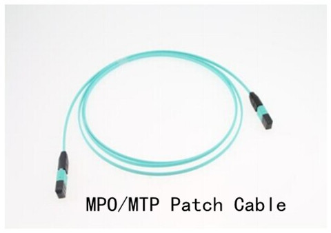
MPO/MTP Patch Cables
MPO/MTP patch cables come into use when 40G or 100G transceivers are employed with MTP/MPO interface, say QSFP+ module (ie. 40G-QSFP-SR4) or QSFP28 optics (ie. JNP-QSFP-100G-SR4). The ends of MTP/MPO fiber cables are terminated with the customer's choice of 12-fiber or 24-fiber MPO connectors. Available in a male-to-male version (left with guide pins) and a female-to-female version (without pins), these cables are used in various applications such as all-optical networking and devices like the above-mentioned 40G/100G optics.
MPO/MTP Trunk Cables
MPO/MTP trunk cables function as a permanent link that connects MPO/MTP modules to each other. Available with 12, 24, 48 and 72 fibers, these cables are used to facilitate rapid deployment of high density backbone cabling in data centers and other high fiber environments reducing network installation or reconfiguration. A 72-fiber MPO/MTP trunk cable can be terminated with 6 MPO/MTP connectors which are manufactured specifically for multi-fiber loose tube or ribbon cable.
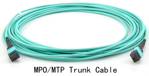
These cables can interconnect cassettes, panels or ruggedized MPO fan-outs, allowing for the flexibility in case any decision is made to change the connector style in the patch panels, new cassettes can be installed with the new connector style on the cross-connect side of the patch panel without having to change the connector on the cable trunk.
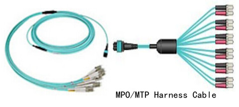
MPO/MTP Harness Cable
MPO/MTP harness cables provide a transition from multi-fiber cables to individual fibers or duplex connectors. They are suitable for many device needs like 100G modules, including CFP, CFP2 and CFP4 series. It provides a reliable, cost-effective cabling system for migrating from legacy 10G to higher speed 40G/100GbE. For instance, 12-fiber MPO to 4 duplex LC can be used to connect four 10G SFP+ (SFP-10G-SR) with one 40G QSFP+ (40G-QSFP-SR4).
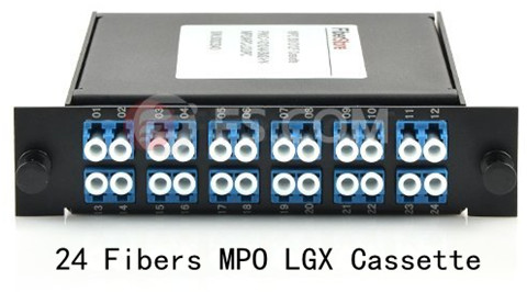
MPO/MTP Cassette Modules
MPO/MTP cassette modules permit rapid deployment of high density data center infrastructure as well as improved troubleshooting and reconfiguration during moves, adds and changes. They enable users to take the fibers brought by a trunk cable and distribute them to a duplex cable. As already assembled units, the MPO cassette modules are fitted with 12 or 24 fibers and have LC, or SC adapters on the front side and MPO/MTP at the rear, this is to say, inside a standard LGX cassette module, there is a hydra cable.
MPO/MTP Cable Heavy Use
Now many big companies are replacing their existing infrastructure with MPO/MTP cassettes in their patch panels to route data for thousands of network electronics, all making MPO/MTP cassettes, patch-cords, connectors and adapters an essential backbone to their infrastructure. If you run one 12-fiber MPO/MTP cable from a cassette on one side of the building to one cassette on the other, you can supply data for 12 connections just like that. The high fiber count in one connector creates endless possibilities. By deploying these different types of MPO/MTP cable in different locations of a data center, there occur several solutions for structured cabling systems that are key to data centers.
Conclusion
MPO/MTP cables come as the solver to meet the demanding request for higher network capacity as data expenses than expected. Fiberstore, as a professional fiber optic product supplier, offers various high-density MPO/MTP cables, trunk and harness versions, patch cords, and cassette module all included. Besides MPO/MTP cables, other cables are also supplied, like LC ST patch cable, LC SC cable, SC SC fiber cable, and so on. You can visit Fiberstore for more information about numerous amounts of cabling assemblies.
Oznake: MPO/MTP cable, MPO/MTP patch cables, MPO/MTP trunk cables, MPO/MTP harness cables, MPO/MTP cassette modules, LC ST patch cable
komentiraj (0) * ispiši * #
