Considerations About Fiber Optic Cable Installation
petak , 15.07.2016.It’s true that fiber optic cable, based on optical technology to carry information between two points, have become increasingly important in fiber optic systems. This cable is often attached with the same or different connectors on the ends to connect devices, for example, LC LC multimode patch cord (LCs on both ends). When used in premises, fiber optic cables can be used as backbone cabling in a standard structured cabling network, connecting network hardware in the computer room. And when applied in optimized fiber optic networks, they go directly to the work area with only passive connections in the links. They can be installed indoors or outdoors using several different installation processes. One of my recent blogs has talked about safety issues about fiber optic cable installation. Today, this article still focuses on its installation, but from other aspects, including the general guidelines, its pulling tension, bend radius, and so on.
When deployed outside, fiber optic cables may be direct buried, pulled or blown into conduit or innerduct, or installed aerially between poles. When used outside, they can be e installed in raceways, cable trays, placed in hangers, pulled into conduit or innerduct or blown though special ducts with compressed gas. The installation process depends on the nature of the installation and the type of cables being used.

Installation General Guidelines
First point to mention is that fiber optic cable is often custom-designed for the installation and the manufacturer may have specific instructions on its installation. So, it’s highly recommended to follow the cable manufacturer’s suggestions. Often, it’s necessary to check the cable length to make sure the cable being pulled is long enough for the run, so as to prevent having to splice fiber and provide special protection for the splices. Of course, it’s better to try to complete the installation in one pull. Prior to any installation, one should assess the route carefully to determine the methods of installation and obstacles that are likely to be encountered.
Pulling Tension
Fiber optic cable is designed to be pulled with much greater force than copper wire if pulled correctly, but excess stress may harm the fibers, potentially causing eventual failure. Cable manufacturers install special strength members, usually aramid yarn, for pulling. Fiber optic cable should only be pulled by these strength members. Any other method may put stress on the fibers and harm them. During installation, swivel pulling eyes should be used to attach the pulling rope or tape to the cable to prevent cable twisting during the pull.
Besides, cables should not be pulled by the jacket unless it is specifically approved by the cable manufacturers and an approved cable grip is used. Tight buffer cable can be pulled by the jacket in premises applications if a large (~40 cm, 8 in.) spool is used as a pulling mandrel. It’s right to wrap the cable around the spool 5 times and hold gently when pulling.
It’s ill-advised to exceed the maximum pulling tension rating. It’s suggested to consult the cable manufacturer and suppliers of conduit, innerduct, and cable lubricants for guidelines on tension ratings and lubricant use.
On long runs (up to approximately 3 miles or 5 kilometers), one should use proper lubricants and make sure they are compatible with the cable jacket. If possible, an automated puller can be used with tension control and/or a breakaway pulling eye. On very long runs (farther than approximately 2.5 miles or 4 kilometers), one should pull from the middle out to both ends or use an automated fiber puller at intermediate point(s) for a continuous pull.
Bend Radius
When there are no specific recommendations from the cable manufacturer, the cable should not be pulled over a bend radius smaller than twenty (20) times the cable diameter. And after completion of the pull, the cable should not have any bend radius smaller than ten times the cable diameter.
Twisting cable
It’s known that twisting the cable can stress the fibers, thus in no case should one twist the cable. (Tension on the cable and pulling ropes can cause twisting.)
Use a swivel pulling eye to connect the pull rope to the cable to prevent pulling tension causing twisting forces on the cable.
Roll the cable off the spool instead of spinning it off the spool end to prevent putting a twist in the cable for every turn on the spool.
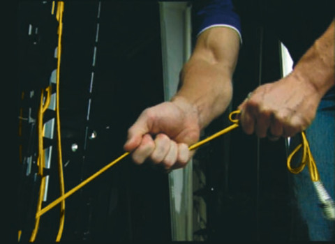
When laying cable out for a long pull, use a “figure 8” on the ground to prevent twisting. The figure 8 puts a half twist in on one side of the 8 and takes it out on the other, preventing twists.
Conclusion
Fiber optic cables have been widely deployed for computer net- works (LANs), closed circuit TV (video), voice links (telephone, intercom, audio), building management, security or fire alarm systems, or any other communications link. With its installation in large scale, it’s of great importance to know some basic points on cable installation discussed in this text. As for the fiber optic cables chosen for project, you can try Fiberstore, whose cables are available in many types, like SC fiber optic cable, LC SC cable, MTP cable. All are test- and quality-assured, suitable for both indoor and outdoor installation.
Oznake: fiber optic cable, connectors, LCs, LC LC multimode patch cord, SC fiber optic cable, cable installation
komentiraj (0) * ispiši * #
Fiber Optic Termination Overview
srijeda , 13.07.2016.It’s known that fiber optic termination methods vary based on the types of fiber optic cable being terminated, the style of connectors or splices used and the termination process appropriate for that connector. Generally speaking, fiber optic cable can be terminated in two ways—connectors that mate two fibers to create a temporary joint and/or connect the fiber to network equipment, and splices which create a permanent joint between the two fibers. Each termination method must have two primary characteristics: good optical performance (low loss and minimal reflectance) and high mechanical strength. As such, the terminations can be made in the right style, installed in a manner that provides low light loss and back reflection and protected against the expected environment, dirt or damage while in use. This passage mainly talks about the first method: connector.
Most fiber optic connectors are plugs or so-called male connectors with a protruding ferrule that holds the fibers and aligns two fibers for mating. Choosing a connector type for any installation should consider if the connector is compatible with the systems planned to utilize the fiber optic cable plant, if the termination process is familiar to the installer and if the connector is acceptable to the customer. If the systems are not yet specified, patch cords with different connectors on each end (e.g. LC ST patch cable) may be necessary.
Choice of Fiber Optic Connector
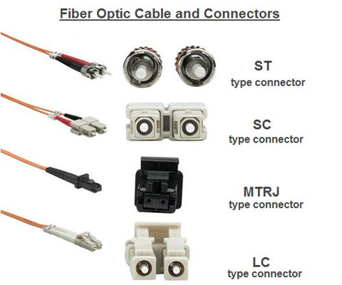
Fiber optic connectors are manufactured in different styles (say, ST, SC, LC, MT-RJ) that attach to the fibers in a fiber optic cable (LC to LC fiber cable single mode) by a number of methods, such as epoxy polish, prepolished/splice, etc.. ST is one of the most popular connectors for multimode networks, like most buildings and campuses. SC is a snap-in connector that is widely used in singlemode systems for it's excellent performance and multimode systems because it was the first connector chosen as the standard connector for TIA-568. LC uses a 1.25 mm ferrule, half the size of the ST. Otherwise, it's a standard ceramic ferrule connector, easily terminated with any adhesive. MT-RJ is a duplex connector with both fibers in a single polymer ferrule. It uses pins for alignment and has male and female versions, basically obsolete nowadays.
Termination Methods
Several termination methods are available for fiber optic cables, and the following passages list three terminations: adhesive termination, crimp/polish termination and prepolished termination.
Adhesive Termination
Epoxy Polish: The fiber is glued into the connector with two-part epoxy and the end polished with special polishing film. This method provides the most reliable connection and lowest losses. The epoxy can be allowed to set overnight or cured in a special oven. A “heat gun” should not be used to cure the epoxy as the uneven heat may not cure all the epoxy or may overheat it which will prevent curing.
Hot Melt: This connector is similar to the epoxy/polish connector but already has the adhesive (a heat set glue) inside the connector. The adhesive is liquefied in an oven before the fiber can be inserted. The fiber is secured when the adhesive cools.
Anaerobic Adhesives: These connectors use a quick-setting adhesive instead of the epoxy. They may use a single part adhesive or an adhesive and set- ting agent. Some adhesives do not have the wide temperature range of epoxies, so they should only be used indoors unless otherwise specified.
Crimp/Polish Termination
These connectors use a crimp on the fiber to hold it in the connector ferrule. The fiber can be polished like an adhesive connector or cleaved with a special tool. Insure the crimp is made properly to prevent fiber pistoning (pulling back or pushing forward in the connector ferrule.)
Prepolished Termination
These connectors have a short stub of fiber already epoxied into the ferrule and polished. Termination requires cleaving a fiber, inserting it into the back of the connector like a splice and crimping. The loss of these connectors will generally be higher than adhesive connectors, since they include the connector loss plus a splice loss in every connector.
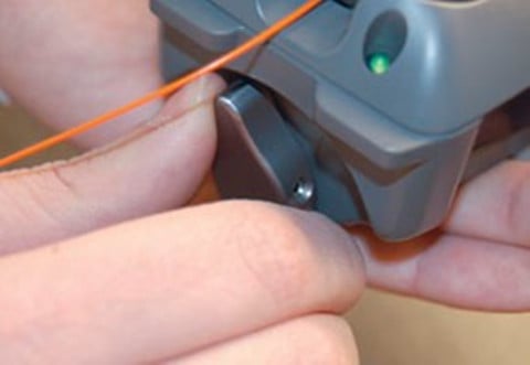
To ensure low loss, the fiber must be cleaved properly, which requires a good cleaver and good technique. Insure the crimp is made properly to prevent fiber pistoning. The termination process can be monitored with a visual fault locator.
Termination Process
Connectors can be installed directly on most cable types, including jacketed tight buffer types like simplex, zipcord and breakout cables, where the where the aramid fiber strength members in the cable are crimped or glued to the connector body to create a strong connector. Connectors can be attached to the 900 micron buffered fibers in distribution cables, but the termination is not as rugged as those made to jacketed cables, so they should be placed in patch panels or boxes for protection. The 250 micron buffered fibers in loose tube cables cannot be easily terminated unless they have a reinforcement called a breakout kit or furcation kit installed, where each fiber is covered by a larger plastic tube. Generally loose tube and ribbon cables are terminated by splicing on a terminated pigtail.
Cables can be pulled with connectors already on them if, and a big if, you can deal with two issues: First, the length must be precise. Too short and you have to pull another longer one (it’s not cost effective to splice), too long and you waste money and have to store the extra cable length. Secondly, the connectors must be protected. Some cable and connector manufacturers offer protective sleeves to cover the connectors, but you must still be much more careful in pulling cables. You might consider terminating one end and pulling the unterminated end to not risk the connectors.
When special tools are required, use them in the appropriate manner. And once installation is completed, connectors should be covered with an appropriate dust cap and stored in a safe location awaiting testing or connection to net- work equipment.
Conclusion
Fiber terminations must also be of the right style to be compatible to the equipment involved and be protected against the environment in which they are installed. When several connector types are all acceptable, or only one connector type is available but not ideal for the installation, the installer should discuss the merits of other types before committing to the project.
Oznake: fiber optic termination, fiber optic cable, connectors, LC ST patch cable, LC to LC fiber cable single mode
komentiraj (0) * ispiši * #
