How Far Can You Bend Your Fiber?
srijeda , 23.11.2016.We know that stress and overstrain is a major enemy of the fiber’s lifespan, so cable installers must ensure that during the installation, fiber cables would not suffer from undesirable stretching or bending. Pulling, pushing and blowing are the three techniques used in wire management, which usually cause minor installation strains even for a seasoned installer. It is unavoidable, but fiber optic cables made of glasses have a limitation of bending ratio or tight diameter. If it do not exceed the certain diameter, the fiber will function well. Therefore it is essential for us to know how far cables can be bent. In fact, the maximum transmission distance of the fiber optic cable depends on the aspects like bend radius, tensile strength and usable duct space, which will be clearer illustrated in the following article.
Bend Radius
Bend radius is the curvature an optical fiber can bend without damage or shortening its lifespan via kinking. The smaller the rated bend radius, the more flexible the fiber. Just check the manufacturer’s spec for bend radius before purchasing the products. If no recommendations are available from the cable manufacturer, the cable should not be pulled into a bend radius smaller than twenty times the cable diameter. For example, a cable with an outer diameter of 5 mm, should not be bent smaller than 100mm radius during installation.
Maintaining proper bend radius is key in preventing service calls due to damage and signal loss in your optical fiber. Bend loss usually occurs when the fiber cable bends is tighter than the cable’s maximum bend tolerance, which might damage the fiber by causing micro cracks.
There are a couple of factors that may mitigate the problems of bend radius and the angles within them. If a fiber cable is being pulled or pushed through an empty duct or mini-duct, obviously there is less resistance to the cable and you can pull/push greater distances. If the coating of the outside of the cable and the inside of the duct are designed to reduce friction, you will be able to achieve greater distances as well.
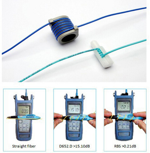
With well-designed bend insensitive fiber patch cables (seen in the above image), you can usually push a fiber cable as far as 90 degree angles in the run with minimized signal loss compared with the traditional fiber patch cables.
Tensile Strength
Just as the bend radius, fiber optic cables also have a maximum tensile strength. If the cable is being pulled through, it is better not to exceed the maximum tensile load. However, if the cable is being installed within a microduct or conduit, pushing the cable will apply no tensile force.
Over-stressing the fibers will not be noticeable until after installation since the cable outer sheath will elongate, whereas glass optical fiber will not. Ideally, a breakaway swivel should be used, however, where this is not possible, the installation crews should use a tension gauge attached to the pull-cord. As a rough approximation, 100 Newtons is equivalent to a 22lbf (pounds-force) load applied directly to the cable.
Usable Duct Space
The full space in the duct is not usable for cables because of horizontal and vertical bends and joints. Usable duct space should be at least 60%. 900µm and 250µm fibers are basically two kinds of fiber patch cables. 900µm fibers can easily be damaged with respect to the storage and wire management. 900 µm kinks easily, but is very flexible and installs easily. Sometimes, you have to balance ease of installation with toughness. The difference between 250um Loose-tube and 900um Tight Buffered Fiber have illustrated in the above article.
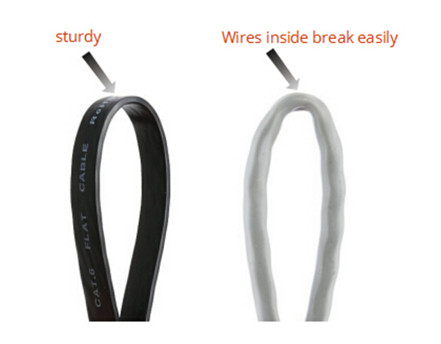
During the cable installation, you must get the fiber through walls—possibly in basements, attics, or crawl spaces, and then through floors, walls and, eventually, through a room to the CPE location. For rugged spaces where your fiber may suffer damage, such as basements or in conduits sharing space with electrical or other wiring, you may need a 3mm rugged sheathed cable that is flexible and crush resistant. The image below shows fiber optic cables being kinked. The flat cat5e cables (left) and common Ethernet cable (right) have different effect after bending.
Therefore, a good rule of thumb to use in planning your fiber drop is below: Bends (angles) = Friction—maximum distance of the pushable fiber
In addition to the above bend radius, here are some other areas to focus on to achieve maximum distance without damaging the cable: signal power and performance requirements for each device or revenue generating unit, locations of required splices, list of cable lengths required. When using duct or cable in conduit, keep in mind that freezing water in the conduit can crush the cable—and it may be wise to use microduct.
Summary
One of the challenges of installing fiber is to choose a cable with a very small bend radius, and it is tough enough to handle many different installation conditions. Once you have selected the appropriate fiber, plan your route to minimize bends and friction. By planning ahead and thinking carefully, you can save money by reducing the costs of those services. FS.COM, as a professional telecom vendor, offers a full range of cable management components, like the patch panels, cable manager & wire duct, fiber enclosures and so on. Some special cables including the bend insensitive fiber patch cables, flat fiber optic cables are also offered. If you have any interest, please send your request to us.
Oznake: Bend radius, wire management, fiber optic cable
komentiraj (0) * ispiši * #
Cost Comparison: Fusion Splicing Versus Pre-terminated System
srijeda , 12.10.2016.Fiber optic joints or termination is a necessary process when installing a network. Every network operators who aim to deploy a next-generation fiber network have to determine how to build a flexible, reliable and long-lasting infrastructure at the lowest possible cost. In general, there are mainly two fiber optic termination methods: splices which create a permanent joint between the two fibers, or connectors that mate two fibers to create a temporary joint. When people decide to use either method, many factors should be taken into account. Today’s article will evaluate both methods from the aspect of cost to help you choose the effective termination method.
Weighting the Two Methods
Besides the features of low loss, minimal reflectance and high mechanical strength, fiber optic termination must be compatible to the environment in which they are installed. Before we come to the cost comparison of these two termination methods, let’s firstly have a brief overview.
Fusion splicing
As it known to all that, splices create a permanent joint between two fibers, so its use is limited to place where cables are not expected to be available for servicing in the future. The most common application for splicing is joining cables in long outside plant cable runs where the length of the run requires more than one cable. There are two types of splices, fusion and mechanical. Fusion splicing is most widely used as it provides for the lowest loss and least reflectance, as well as providing the strongest and most reliable joint.
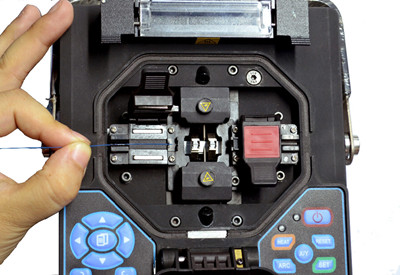
Fusion splicing machines are usually called fusion splicer available on the market that splice a single fiber or a ribbon of 12 fibers at one time. The above picture shows how to splice a fiber optic jumper. Virtually all single-mode splices are fusion. Fusion splices are made by "welding" the two fibers together usually by an electric arc. To be safe, you should not do that in an enclosed space like a manhole or an explosive atmosphere, and the equipment is too bulky for most aerial applications, so fusion splicing is usually done above ground in a truck or trailer set up for the purpose.
Today's single-mode fusion splicers are automated and you have a hard time making a bad splice as long as you cleave the fiber properly. Fusion splicers cost thousands US dollars (up to $5,000), but the splices only cost a few dollars each. The following part display the main features of the fusion splicing:
- Typical average optical losses of 0.05dB or lower
- Not de-mateable
- Special installation skills needed
- Tools sensitive to the environment
- Relatively long installation time
- Standard organizer techniques required
Pre-terminated System
Pre-termination is the alternative termination method popular on the market. Cables and fibers are terminated to a connector in the factory. When carefully planned, splicing jobs for specialized technicians can be limited to the network construction phase. But provisioning, churn and network testing can be performed by technicians without specific fiber skills, because the organizers can be very simple.
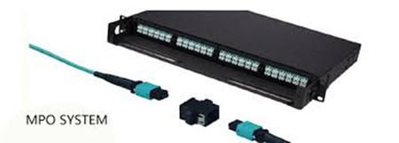
With pre-connectorized products, the connection time is reduced from 20 to less than 5 minutes, including the connector cleaning step. When connecting fibers with connector technology, there is no issue of environmental sensitivity. What’s more, connectors are accessible on the outside of the network element, reducing the need to access a product and the risk of disturbing other lines. The image below shows the MPO pre-terminated cables.
Factory pre-termination is also compatible with optical budget requirements by selecting the appropriate grade as defined by the international IEC standards. When properly planned, pre-connectorized
products do not add extra connectivity points, thus eliminating extra optical loss or reflections. In all, the most obvious features of the pre-terminated system lies in the following part:
- Typical losses of 0.15dB or less
- Fully de-mateable
- No special installation skills required
- Reduced installation time
- Very simple organizer systems
- Insensitive to environmental conditions
Cost Comparison
The start-up costs for the fusion splice are significantly higher, as fusion splicers can be very expensive. Even the cheapest fusion splicer will cost nearly $2,900 (FS-F600 Fusion Splicer from FS.COM) more than the most expensive crimp kit. Not counting the initial start-up costs, splices will run anywhere from $7.20 to $8.25 per splice, which is much lower than the pre-terminated connector. The following image shows the vivid comparison between fusion splicing and pre-terminated system.
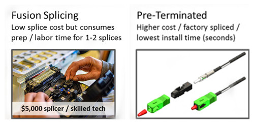
As for the pre-terminated connector, the most significant advantage is the wire management hardware involved. A pre-terminated connector requires no additional hardware over a standard connector. And it is faster to terminate a crimp connector, saving labor time ($0.75 per splice), and splicing also requires additional material costs in the form of splice protectors ($0.40 per splice). Fiber splicing technicians have specialized training that makes them expensive when compared to someone simply plugging things in. The additional material and closet space for managing splices can cost an additional $6.05-7.10 per connector. But with a little careful planning as to lengths of fibers needed, pre-terminated fibers can be installed quickly and with no training.
In all, fusion splicing makes a lot of sense for trunk fibers and locations where there are anywhere from 48 to 192 fibers to splice. In the drop locations, where there may be only one or two splices at each location, the setup time for each location may negate any cost savings from fusion splicing.
Making the Choice
In comparing pre-termination and fusion splicing, both have their inhered advantages. Fusion splicers offer many advantages in the premises environment, from being lightweight and compact to operating on a battery. These new units minimize setup time and are ideal for use in locations where space is tight. In addition, the total splice and heater cycle time is less than one minute, thereby enabling technicians to move through many termination locations quickly.
However, we cannot deny the fact that the start up cost of the fusion splicing is huge, thus customers that can’t deal with budget are going to demand pre-terminated connectors. Pre-terminated solutions offer the most benefits: It’s easy to install pret-terminated cables, and because they’re available in custom lengths, it’s easy to get the exact lengths required to limit the excess slack. Many more users will rely on the pre-terminated trunk cables and sacrifice the inconvenience of dealing with slack, because it offers faster deployment.
As you get into significantly higher fiber counts, fusion splicing could save time over installing connectors. While for those who don’t have a fusion splicer or splicing experience, may want to consider pre-terminated connectors. FS.COM offers both fusion splicer and per-terminated cables, our products are integrated, holistic physical infrastructure solutions that guarantee a reliable and stable performance for your network. Please contact us if you need help.
Oznake: Fusion Splicing, Pre-terminated, wire management, fiber optic jumper
komentiraj (0) * ispiši * #
