Introduction to Several Cable Ties
srijeda , 30.11.2016.Owing to its low cost and ease of use, cables ties are ubiquitous in a wide range of telecom applications. Generally, cable ties, zip ties, or tie wraps are designed to hold items together, primarily the electric cables or wires. It is treated as a type of fastener. There are multiple types of cable ties available on the market today, such as nylon cable ties, Stainless Steel cable ties, and Velcro cable ties, etc. And each of them has their own features. So this article will introduce three common cable ties for you to select which cable ties suitable for the wire management.
Nylon Cable Ties
The common zip ties, normally made of nylon, has a flexible tap section with teeth that engage with a pawl in the head to form a ratchet so that as the free end of the tape section is pulled the tie-wrap tightens and does not come undone. The Nylon material possesses an outstanding balance of properties, combined strength, moderate stiffness, high service temperature, and a high level of toughness.
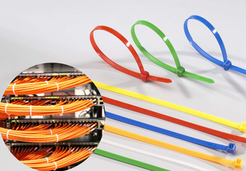
Nylon cable ties are particularly resistant to repeated impact. They have a low coefficient of friction, and excellent abrasion resistance. But they should be stored in cool dry areas, out of direct sunlight, and sealed in the original packaging material. These measures will extend cable tie performance levels indefinitely. Nylon cable ties can be broadly divided into several cable ties: Colored Cable Ties, ID Marker Ties, Eyelet Cable Ties, and Releasable Cable Ties. An article entitled “Nylon, Velcro and Stainless Steel Cable Ties” has provided some detailed information about these cable ties.
Velcro Cable Ties
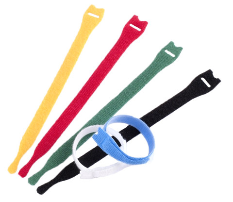
Velcro Cable Ties is made of soft hook and loop material, also known as hook and loop cable ties. They deliver reliability by protecting against over-tension of high-performance fiber and copper cables. These ties are adjustable, releasable, and reusable to effectively support frequent moves, adds, and changes (MACs). Moreover, a wide range of designs, sizes and colors provide flexibility and an aesthetically pleasing appearance. The key benefits of velcro cable ties are reliability, scalability and aesthetics. Velcro cable ties are very useful for computer and other data-cables as they will not crush the cables and cause damage.
Stainless Steel Cable Ties
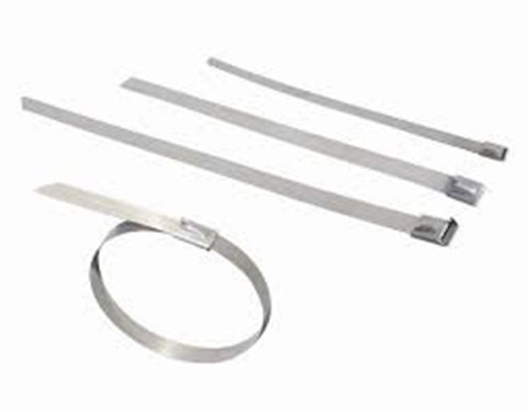
The stainless steel cable ties either naked or coated with a rugged plastic, cater for exterior application and hazardous environments. This type of cable ties are made of stainless steel, which makes them much stronger and able to achieve a tensile strength of up to 400 pounds or more. Differ from plastic cable ties, you don’t need to pull this cable tie to a tight close but through a through a self-locking mechanism. This mechanism can stand alone or be part of a ball lock system. What this locking mechanism does is add strength to the tie and ensure that it doesn’t wear down or corrode when the temperatures get too hot or cold. The best part about this locking device is that you don’t need much strength to feed the tie through. Stainless steel cable ties are ideal for applications that require a high-level of protection against corrosion and environmental conditions, which may cause typical nylon cable ties to disintegrate.
At the end of this article, one misunderstanding about cable ties needs to be explained. Cable ties, especially the plastic cable ties are generally viewed as single-use devices; they are typically cut off rather than loosened and reused. However, if a closed loop needs to be opened again, rather than destroying the cable tie by cutting, it may be possible to release the ratchet from the rack. While some cable ties are designed for reuse with a tab that releases the ratchet, in most cases a sewing needle or similar object will need to be interposed between the ratchet and the rack. Ties reused in this way will be weaker than new ones.
Conclusion
To sum up, this article has briefly introduced three cable ties. Each should be suitable for the unique applications. No matter what your installation requires, FS.COM is sure to have the exact zip or cable tie that you need. Please don’t feel hesitate to contact us.
Oznake: cable ties, nylon cable ties, Stainless Steel cable ties, Velcro cable ties
komentiraj (4) * ispiši * #
MTP/MPO Fiber Cable and its Application in 40G Network
petak , 25.11.2016.As the request for greater bandwidth and higher-density fiber optic connections within data centers continues, these requirements must be met by choosing the right type of connectivity. MPO/MTP fiber cable is specially designed for applications for all networking and device needs like 40G modules. It uses a high-density multi-fiber connector system built around precision molded MT ferrule, which are available in UPC and APC polish. It supports both multimode and single-mode applications, and optional lengths available. There are two main MTP/MPO cables types: MPO/MTP trunk cables and MPO/MTP harnesses cables. The following article will have a brief introduction to them individually.
MPO/MTP Standard Trunk Cables
Available in 12, 24, 48 and 72 fibers, MPO/MTP trunk cables work as a permanent link that connects MPO/MTP modules to each other. These cables are used to facilitate rapid deployment of high density backbone cabling in data centers and other high fiber environments reducing network installation or reconfiguration. A 72-fiber MPO/MTP trunk cable (see in the below image) can be terminated with 6 MPO/MTP connectors which are manufactured specifically for multi-fiber loose tube or ribbon cable. The MPO/MTP Trunk cable is designed for Data Center Applications.
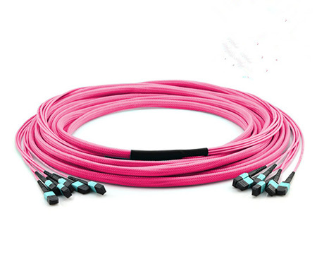
These cables can interconnect cassettes, panels or ruggedized MPO fan-outs, allowing for the flexibility in case any decision is made to change the connector style in the patch panels, new cassettes can be installed with the new connector style on the cross-connect side of the patch panel without having to change the connector on the cable trunk.
FS.COM offer single-mode (OS2) and multimode (10G OM3, 10G OM4) MPO/MTP Cable. Single-mode MPO/MTP cable is primarily used for applications involving extensive distances, 10G MPO/MTP cable provide 10G data transfer speeds in high bandwidth applications and they are 5 times faster than standard 50um fiber cable. Work with both VCSEL laser and LED sources, that means, the MTP/MPO trunk cables also provide 40G/100G MPO/MTP trunk cable.
MPO/MTP Harnesses Cables
The MPO/MTP Harnesses cable is MPO/MTP on one end, with single-fiber connectors on another end, single-fiber connector interface available in SC, ST, LC, MTRJ in forms of simplex or duplex channeling. It provides a reliable, cost-effective cabling system for migrating from legacy 10G to higher speed 40G/100GbE. They are suitable for many device needs like 100G modules, including CFP, CFP2 and CFP4 series. MPO/MTP Harnesses cable are available in SM (OS2), MM (OM3/OM4). You could select the suitable fiber according to your own needs with the selection of 12/24/72 fiber cores. The following picture shows the OS2 Fiber Optic Harness Cable.
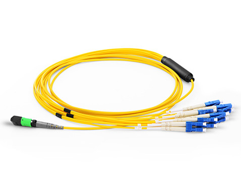
The MPO/MTP harnesses cable application for data centers requiring quick infrastructure deployment with extended reach that want to maintain bandwidth throughout the infrastructure, its design cater for up-scaling needs and future technologies growth, it’s the best solution, which covers all fiber optic cabling needs in all areas of Data Center.
High-density MTP/MPO Cables for 40G Connection
IEEE 802.3ba 40 Ethernet Standard was ratified in June 2010. This standard specifies MPO connectors for standard-length MMF connectivity. MMF employs parallel optics using MPO interconnects for 40GbE transmission. More specifically, 40G is implemented using eight of the twelve fibers in a MPO connector. Four of these eight fibers are used to transmit while the other four are used to receive. Each Tx/Rx pair is operating at 10G.
Figure 1 shows a Type B MTP female trunk cables for 40GBASE SR4 QSFP+ and multi-fiber migration networks.
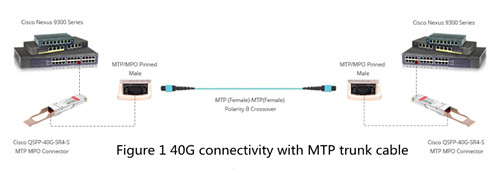
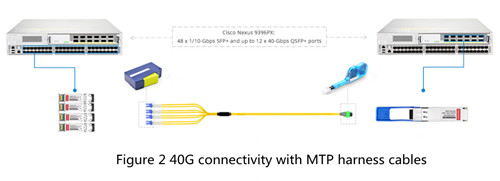
Figure 2 shows how to extend your Cisco Nexus 10GBASE-LR networks up to 40G with MTP cable and 4x10GBASE-LR SFP+ transceiver for your high speed data center solution. The 4x 10GBASE-LR SFP+ transceivers interconnection with 1x 40GBASE-LR QSFP+ transceivers (QSFP-40GE-LR4) by one MTP to 4LC harness cable directly.
Fiberstore MPO-based fiber cabling solutions provide a fast, simple and economical way for 40G applications. Certainly, 40G fiber cabling solutions are not only limited to MPO/MTP fiber cables. QSFP cables, especially direct attach copper cables are also recommended. 40G direct attach cable provides a cost-effective solution for high-density network connectivity. You can see the detailed information in an article entitled “40G Direct Attach Cable (DAC) Cables Overview”.
Conclusion
To sum up, MPO/MTP cabling have proven to be an excellent solution for delivering 10G, 40G and 100G transmission, especially within a data center environment. It provides a flexible, high density option for quickly connecting services. FS.COM offers various high-density MPO/MTP fiber optic cables, trunk and harness versions, patch cords, and cassette module. The MPO/MTP fiber cables are tested with guaranteed quality, and they can be installed easily, which saves time and money. Besides MPO/MTP cables, other cables are also supplied, like LC to ST fiber cable, LC SC cable, SC SC fiber cable, and so on.
Oznake: MTP/MPO fiber Cable, LC to ST fiber cable, QSFP-40GE-LR4
komentiraj (0) * ispiši * #
How Far Can You Bend Your Fiber?
srijeda , 23.11.2016.We know that stress and overstrain is a major enemy of the fiber’s lifespan, so cable installers must ensure that during the installation, fiber cables would not suffer from undesirable stretching or bending. Pulling, pushing and blowing are the three techniques used in wire management, which usually cause minor installation strains even for a seasoned installer. It is unavoidable, but fiber optic cables made of glasses have a limitation of bending ratio or tight diameter. If it do not exceed the certain diameter, the fiber will function well. Therefore it is essential for us to know how far cables can be bent. In fact, the maximum transmission distance of the fiber optic cable depends on the aspects like bend radius, tensile strength and usable duct space, which will be clearer illustrated in the following article.
Bend Radius
Bend radius is the curvature an optical fiber can bend without damage or shortening its lifespan via kinking. The smaller the rated bend radius, the more flexible the fiber. Just check the manufacturer’s spec for bend radius before purchasing the products. If no recommendations are available from the cable manufacturer, the cable should not be pulled into a bend radius smaller than twenty times the cable diameter. For example, a cable with an outer diameter of 5 mm, should not be bent smaller than 100mm radius during installation.
Maintaining proper bend radius is key in preventing service calls due to damage and signal loss in your optical fiber. Bend loss usually occurs when the fiber cable bends is tighter than the cable’s maximum bend tolerance, which might damage the fiber by causing micro cracks.
There are a couple of factors that may mitigate the problems of bend radius and the angles within them. If a fiber cable is being pulled or pushed through an empty duct or mini-duct, obviously there is less resistance to the cable and you can pull/push greater distances. If the coating of the outside of the cable and the inside of the duct are designed to reduce friction, you will be able to achieve greater distances as well.
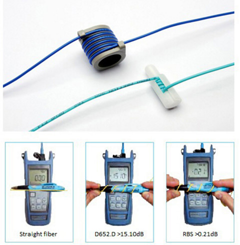
With well-designed bend insensitive fiber patch cables (seen in the above image), you can usually push a fiber cable as far as 90 degree angles in the run with minimized signal loss compared with the traditional fiber patch cables.
Tensile Strength
Just as the bend radius, fiber optic cables also have a maximum tensile strength. If the cable is being pulled through, it is better not to exceed the maximum tensile load. However, if the cable is being installed within a microduct or conduit, pushing the cable will apply no tensile force.
Over-stressing the fibers will not be noticeable until after installation since the cable outer sheath will elongate, whereas glass optical fiber will not. Ideally, a breakaway swivel should be used, however, where this is not possible, the installation crews should use a tension gauge attached to the pull-cord. As a rough approximation, 100 Newtons is equivalent to a 22lbf (pounds-force) load applied directly to the cable.
Usable Duct Space
The full space in the duct is not usable for cables because of horizontal and vertical bends and joints. Usable duct space should be at least 60%. 900µm and 250µm fibers are basically two kinds of fiber patch cables. 900µm fibers can easily be damaged with respect to the storage and wire management. 900 µm kinks easily, but is very flexible and installs easily. Sometimes, you have to balance ease of installation with toughness. The difference between 250um Loose-tube and 900um Tight Buffered Fiber have illustrated in the above article.
During the cable installation, you must get the fiber through walls—possibly in basements, attics, or crawl spaces, and then through floors, walls and, eventually, through a room to the CPE location. For rugged spaces where your fiber may suffer damage, such as basements or in conduits sharing space with electrical or other wiring, you may need a 3mm rugged sheathed cable that is flexible and crush resistant. The image below shows fiber optic cables being kinked. The flat cat5e cables (left) and common Ethernet cable (right) have different effect after bending.
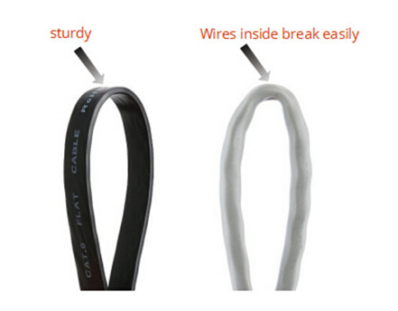
Therefore, a good rule of thumb to use in planning your fiber drop is below: Bends (angles) = Friction—maximum distance of the pushable fiber
In addition to the above bend radius, here are some other areas to focus on to achieve maximum distance without damaging the cable: signal power and performance requirements for each device or revenue generating unit, locations of required splices, list of cable lengths required. When using duct or cable in conduit, keep in mind that freezing water in the conduit can crush the cable—and it may be wise to use microduct.
Summary
One of the challenges of installing fiber is to choose a cable with a very small bend radius, and it is tough enough to handle many different installation conditions. Once you have selected the appropriate fiber, plan your route to minimize bends and friction. By planning ahead and thinking carefully, you can save money by reducing the costs of those services. FS.COM, as a professional telecom vendor, offers a full range of cable management components, like the patch panels, cable manager & wire duct, fiber enclosures and so on. Some special cables including the bend insensitive fiber patch cables, flat fiber optic cables are also offered. If you have any interest, please send your request to us.
Oznake: Bend radius, wire management, fiber optic cable
komentiraj (0) * ispiši * #
Difference Between 50 Ohm and 75 Ohm Coaxial Cable
četvrtak , 17.11.2016.People know much about the coaxial cables, but they know little about the different impedance of coaxial cables, namely 50 Ohm and 75 Ohm coaxial cables. Even many optical manufacturers fail to adequately explain the difference between the two types of coax and why they need one type over the other. Therefore, today’s article will define some of the most critical concepts regarding coaxial cable technology, and shed light on the difference between these two coaxial types.
What's Ohm?
An Ohm is the unit of resistance used to measure the flow of electrical current through a circuit. In the most basic applications where we are dealing with DC or Direct Current electricity, we are measuring the resistance in Ohms. It is known that the smaller the Ohm, the better the performance. So a 50 Ohm cable provides much better results than a 75 Ohm cable. However, you can find the 75 Ohm cables are everywhere inside your home from the back of the TV to cable & satellite TV boxes and internet routers. Why does the 75 Ohm coaxial cables have the poor impedance but still win large popularity in the home network? In fact, there really is no good or bad impedance, just the right impedance for your application. For the detailed information about these two types of coaxial cables, please read on.
Shedding Light on Coaxial Cable
Coaxial cable, as one type of the bulk fiber optic cable, is comprised of three main components—center conductor, dielectric and shield. Center conductor as the name implies, is in the middle of the coaxial cable that can be made of either solid or stranded wire. Surrounding the center conductor is something called the dielectric. The dielectric acts as a buffer of sorts to keep the center conductor isolated and straight. Finally, on the outside of the dielectric is the coaxial cable’s shield, which is usually a combination of Copper and Aluminum foil and/or wire braid. The shield is then coated by something like PVC to insulate it from the environment. As noted before, coaxial cable can be divided into two types according to different impedance: 50 Ohm and 75 Ohm.
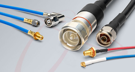
50 Ohm Coaxial Cables: The Forgotten Impedance
First, let’s look at 50 Ohm Coaxial Cables. Experimentation in the early 20th century determined that the best power handling capability could be achieved by using 30 Ohm Coaxial Cable, whereas the lowest signal attenuation (LOSS) could be achieved by using 77 Ohm Coaxial Cable. However, there are few dielectric materials suitable for use in a coaxial cable to support 30 Ohm impedance. Thus, 50 Ohm Coaxial Cable was selected as the ideal compromise; offering high power handling AND low attenuation characteristics.
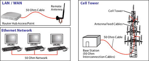
With 50 Ohm coaxial cables being the best compromise solution, practically any application that demands high power handling capacity, i.e. 100 watts or more, will use 50 Ohm Coaxial Cable. A good rule of thumb is that any device that functions as a transmitter or transceiver tends to use 50 Ohm Coaxial Cable. This includes devices such as CB/Ham Radios, Broadcast Radio/TV Transmitters, Wi-Fi and Cellular Phone Repeaters and 2-Way Radios seen in the below image. And since 50 Ohm cables aren't as ubiquitous as 75 Ohm cables in the home network, running cable is potentially more difficult if your building is not pre-wired for it. Seriously, the cable is noticeable bigger than a 75 Ohm.
75 Ohm Coaxial Cable is the Way to Go
However, not every case warrants high power handling, so 50 Ohm Coaxial Cable is not appropriate for every application. When the objective is to ensure that the signal gets through the cable in the most efficient way possible, losing very little signal strength in the process, 75 Ohm Coaxial Cable is the way to go. This includes devices such as Satellite and Cable TV Receiver Boxes, High Definition Televisions, AM/FM Radio Receivers and Police Scanners as you can see in the following image.
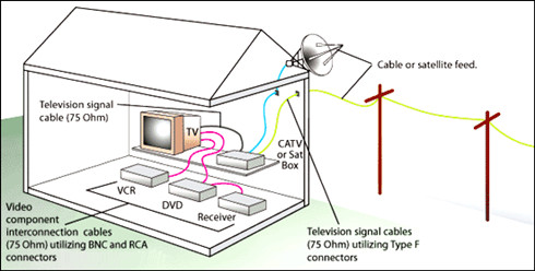
With the features of low attenuation and capacitance effectively, 75 Ohm coaxial cable becomes the cable of choice for practically all types of digital audio, digital video and data signals. This is also the reason why every cable TV company uses 75 Ohm coax for distributing its digital video channels as well as its broadband internet data signals. Additionally, direct broadcast satellite dishes and over-the-air HDTV antennas require 75 Ohm Coaxial Cable to ensure that all of the digital channels transfer down the cable with the lowest loss and distortion possible.
75 Ohm cables are the standard coax cable and they're commonly used and are often pre-wired in many homes and businesses. In all, 75 Ohm is primary used for video and audio, hence why it's rapid adoption.
Conclusion
To sum up, the 75 Ohm cable is the primarily utilized for the transmission of a video signal. In the case of 50 Ohm cable, it is a data signal that is for the most part being transmitted. To put it simply, 75 Ohm is for pictures and 50 Ohm is for information. FS.COM is committed to provide the best services and first-class fiber optics to all of our customers. Besides the copper cable (coaxial cables and twisted cables), fiber optic cables are also provided with large selection and high quality. Feel welcome to contact us.
Oznake: 50 Ohm, 75 Ohm, Coaxial Cable, bulk fiber optic cable
komentiraj (0) * ispiši * #
C3KX-NM-10G Network Module Overview
petak , 11.11.2016.Questions like whether a 1G SFP can be used on the SFP+ port of the switch and support 10G data rate are frequently asked by overall users. Generally, you will get the answer “no”. Because Most (95+%) SFPs and SFP+s will only run at the rated speed, no more, no less. Even though SFP and SFP+ have the same port size, it doesn’t mean that you can insert a SFP in a SFP+ port to achieve a 10G connectivity. Not to mention that some SFP+ port can only support 10G SFP+ optics. However, this article will introduce a Cisco Network module in Cisco Catalyst 3750-X and 3650-X Series switches that can both support 1 GbE SFP and 10 GbE SFP+ transceivers.
C3KX-NM-10G Network Module
The Cisco Catalyst 3750-X and 3560-X series switches support four optional network modules for uplink ports, namely C3KX-NM-1G (four GbE port network module), C3KX-NM-10G (two 10GbE SFP+ ports network module with four physical ports with two SFP+ and two regular SFP ports), C3KX-NM-10GT (two 10GB-T ports network module), C3KX-SM-10G (service module with two 10GbE SFP+ ports network module for Netflow and MACsec encryption). C3KX-NM-10G module on the Cisco Catalyst 3750-X and 3560-X has two installation screws on each side, which make it easy to switch things out and make new connection without a fuss. What’s more, when business demands changes, the C3KX-NM-10G network module allows customers to only upgrade their modules from 1 GbE to 10 GbE without replacing a comprehensive upgrade of switch.
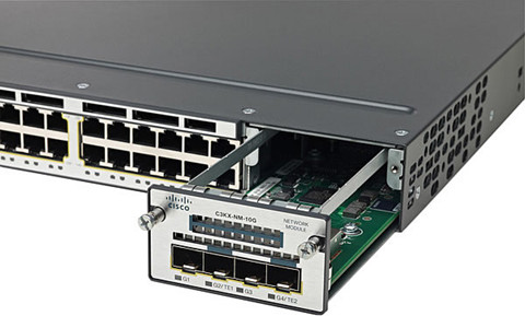
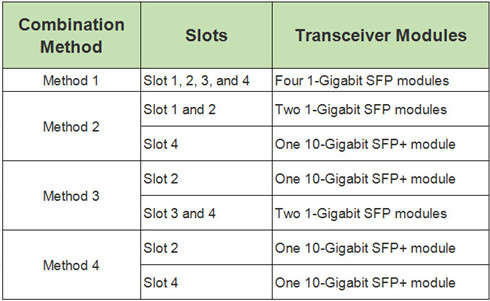
As the above image shows, the C3KX-NM-10G network module has four slots—two SFP+ slots and two SFP slots. These four slots usually work in pair, with one pair supporting 1 GbE data rate and the other achieving 10 GbE. Note that you must use the same form factor transceiver in a pair and never mix the SFP module with SFP+ module. SFP+ can’t auto-negotiate down to 1G to support with SFP module.
To put it simply, let’s name the port from left to right as slot 1, slot 2, slot 3, slot 4. Usually a 10-Gigabit SFP+ module takes precedence over a 1-Gigabit SFP module. But it’s another case when an SFP module is first inserted in Slot 1 and has link. For example, if the SFP in Slot 1 retains link, you insert an SFP+ module in Slot 2 and it will not operate. If the SFP module in Slot 1 is shut down or removed, the SFP+ module in Slot 2 turns on. The SFP module in Slot 1 does not work as long as an SFP+ module is in Slot 2. The following chart concludes the accessible combination of SFP and SFP+ modules.
Suitable Cisco Transceivers for C3KX-NM-10G Network Module
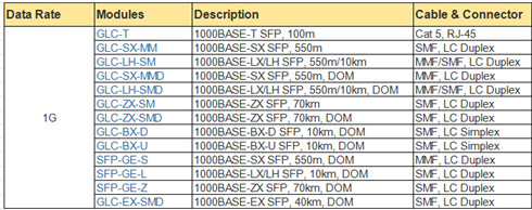
As note before, C3KX-NM-10G module on the Cisco Catalyst 3750-X or 3560-X series switch can both support 1 Gigabit Ethernet and 10 Gigabit Ethernet data links. We will list the available Cisco modules attached with detailed information in the below charts.
Cisco SFP transceiver for C3KX-NM-10G module:
Cisco SFP+ transceiver for C3KX-NM-10G module:

There are many other compliant Cisco SFP+ DAC and AOC cables that I haven’t listed above, if you are interested, you can visit fs.com.
Conclusion
This post lists all of the functions of the Cisco C3KX-NM-10G network module, all the basic and advanced features and tells you how to select the compliant Cisco SFP modules and SFP+ modules. If you want to expand your database from 1GbE to 10GbE, with the Cisco C3KX-NM-10G network module, you only need to upgrade your Cisco SFP and plug it with a brand new SFP+ transceiver, then that’s it.
Oznake: C3KX-NM-10G, SFP, Cisco SFP
komentiraj (0) * ispiši * #
Introduction to Fiber Optic Attenuator
srijeda , 09.11.2016.Fiber optic attenuators are often used to control the optical signal strength in fiber optic links. For example, in a DWDM based system, the DWDM employs multiple wavelengths and channels in different communication protocols and bit rates requiring precise tuning of the power levels of the channel signals. Fiber optic attenuators are often used to adjust the optical power signal strength. How exactly does the fiber optic attenuator work? This article might provide you some information.
What Is Fiber Optic Attenuator?
A fiber optic attenuator, also called as an optical attenuator, can simulate the optical loss that could be caused by a long period of fiber. Put it simply, for a fiber optic receiver, too much light can overload it and degrade the bit error ratio. Therefore, the light power at the receiver end should be reduced. Fiber optic attenuators fit the requirement perfectly. This usually happen when the transmitter delivers too much power like the single-mode system, or the transmitter is simply too near to the receiver. Optical attenuators can be divided into two types—fixed and variable attenuators.
Fixed Fiber Optic Attenuators
Fixed fiber optic attenuator, also called fixed plug type or fixed build-out fiber optic attenuator, is used in fiber optic communications to reduce the optical fiber power by a certain level. Fixed fiber optic attenuators have fixed values that are specified in decibels from 1dB to 30dB. Usually, it has a male plug connector at one side to allow the attenuator to be plugged directly into receiver equipment or adapters in patch panel, and has female type fiber optic adapter at the other side to allow the patch cords to plug in (seen in the below image).
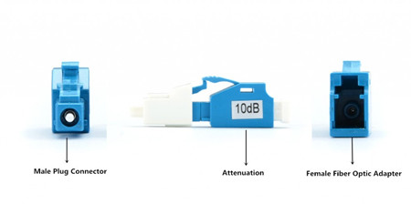
Fixed fiber optic attenuator is based on the connector type and the attenuation level. For instance, LC 10dB fixed fiber optic attenuator means this attenuator use LC fiber optic connector, and it can reduce the optical fiber power level by 10dB. Their applications include telecommunication networks, optical fiber test facility, LAN and CATV systems.
Variable Fiber Optic Attenuators
Variable fiber optic attenuators (or adjustable fiber optic attenuator) are with adjustable attenuation range. It usually is inline type, the appearance like fiber optic patch cord; it is with an adjustable component in the middle of the device to change the attenuation level to a certain figure. There are also handheld variable fiber optic attenuators; they are used as test equipment, and we have the inline fiber optic attenuators.
How to Use Fixed Fiber Optic Attenuator?
In general, multimode systems do not need attenuators as the multimode sources, VCSELs, rarely have enough power output to saturate receivers. Instead, single-mode systems, especially short links, often have too much power and need optical attenuators. Therefore, fixed fiber optic attenuators are usually single-mode types. Fixed fiber optic attenuators should be always installed at the receiver end of the link (X in the drawing). This is because it’s more convenient to test the receiver power before and after attenuation or while adjusting it with your power meter at the receiver, plus any reflectance will be attenuated on its path back to the source.
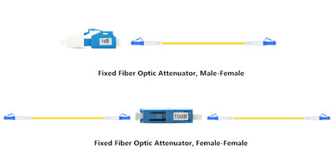
For female to male fixed fiber optic attenuators, we can plug the fiber cable to the female fiber optic adapter of the attenuator. And then plug the male plug connector of the attenuator to the equipment directly. For female to female fixed fiber optic attenuators, we should plug the two patch cords to the two female fiber optic adapter of the attenuator (shown in the above figure).
Conclusion
Optical attenuators can be divided into four classes depending on the type of ports, namely, SC, LC, FC, ST optical attenuators. FS.COM as a attenuator manufacturer, provide several types of attenuator as well as other related products such as adapter, multiplexer, optical converter and so on. Our fixed fiber optic attenuators offer low return loss, high mode stability and a variety of attenuation values. Even you are not clear about some specifications which you need, you can directly visit the fiber store.
Oznake: Fiber Optic Attenuator, DWDM, CWDM, Fixed Fiber Optic Attenuators
komentiraj (0) * ispiši * #
Choosing a Fiber Switch
srijeda , 02.11.2016.Do you have the experience of setting up a fiber switch for your network system? Or do you feel distressed for choosing an ideal fiber switch for you clients? Fiber switch is the dispensable telecom device that joins multiple devices within one network. There are many factors to be considered before you make a product choice. One of the key points is that fiber switch must accommodate severs and storage devices both for the present and future proof. Today’s article has concluded the frequently asked questions about selecting a fiber switch, and provide some assistance to you.
Fiber Switch Overview
Before we come to the main part, let’s have a brief overview of the fiber switches. Generally, fiber switch is broadly divided into two main category—modular and fixed configuration. The modular fiber switch just like the Cisco 4500 series switch (seen in the below image), allows you to add expansion modules into switched as needed, thereby delivering the best flexibility to address changing networks.

While the fixed configuration fiber switch, as the name implies, are switches with fixed number of ports and are typically not expandable. Cisco Catalyst 3750 is the good example of this. The fixed configuration switch category is further broken down into: unmanaged switch, smart switch and managed L2 and L3 switch. Each of them can be used in different situation.
How to Choose a Fiber Switch?
In the previous article entitled “Why Choose to Use a Managed Ethernet Switch?”, it mentioned the reasons why people should use managed switch other than unmamaged switch. Mangaed switch can give you better control over LAN traffic and offer advanced features like remote management, Redundancy, QoS services. Besides the above factors, some common features about choosing a right fiber switch is listed below.
Transmission Speed
Fiber switches are typically in Fast Ethernet, Gigabit Ethernet, 10 Gigabit and even 40/100 Gbps speeds. These switches have a number of uplink ports and downlink ports. Downlinks connect to end users, and uplinks connect to other Switches or to the network infrastructure. Currently, Gigabit speed is the most popular interface speed though Fast Ethernet is still widely used, especially in price-sensitive environments. 10 Gigabit has been growing rapidly, especially in the data center and, as the cost comes down, it will continue to expand into more network applications. And the 40G/100G is still emerging and will be mainstream in a few years. For example, the commonly used Catalyst 3750 is armed with 48 Ethernet 10/100/1000 ports with IEEE 802.3af PoE and 4 SFP uplinks, which is suitable for 1G application.
Number of Ports
Fiber switches typically come in 5, 8, 10, 16, 24, 28, 48, and 52-port configurations. These ports may be a combination of SFP/SFP+ slots for fiber connectivity, but more commonly they are copper ports with RJ-45 connectors on the front, allowing for distances up to 100 meters.
PoE Versus Non-PoE
Power over Ethernet (PoE) is a capability that facilitates powering a device (such as an IP phone, IP Surveillance Camera, or Wireless Access Point) over the same cable as the data traffic. One of the advantages of PoE is the flexibility it provides in allowing you to easily place endpoints anywhere in the business, even places where it might be difficult to run a power outlet.
However, switches have a power budget set aside for running the switch itself, and also an amount of power dedicated for PoE endpoints. For example, PoE switches according to 802.3af standard deliver power up to 15.4 Watts on a switch port, and IEEE 802.3at (also known as PoE+) delivers power up to 30 Watts on a switch port. For most endpoints, 802.3af is sufficient but there are devices, such as Video phones or Access Points with multiple radios, which have higher power needs. It’s important to point out that there are other PoE standards currently being developed that will deliver even high levels of power for future applications.
Whether to choose a PoE switch or non-PoE switch, you need to consider the features associated with the PoE capacity as well as your power needs. When connecting to desktops or other types of devices which do not require PoE, the non-PoE switches are a more cost-effective option.
Conclusion
When you are preparing a new installation with Fiber running, choose a suitable switch is essential. But if you search on the internet, you will find there are many types of switches on the market. Take Cisco as an example, it had launched a series of switches, and each has different performance. I hope this article can provide you some steep learning curve about fiber switches. It is advisable for you to ask an expert for help, or you may waste your money.
Oznake: Fiber switch, Cisco 4500, Catalyst 3750
komentiraj (0) * ispiši * #
