SMF&MMF 40G QSFP+ Transceiver Overview
srijeda , 27.04.2016.The demand for better network throughput and performance has never ceased. Instead, it has become more and more vigorous. The server consolidation, virtualization, as well as networking-service performance improvements, all these have pushed the necessity for dense 40GbE switch connections in data centers.
But when migrating to 40GbE from10GbE, some companies or organizations are challenged by two main factors in re-configuring the physical layer of the network: firstly, the possible reduced reach of the OM3/OM4 multi-mode optics from 10GBASE-SR (300/400 m) to 40GBASE-SR4 (100/150m), and secondly, the need to upgrade the existing fiber optic cabling plant so as to support the IEEE-defined 40GBASE-SR4 parallel optics. In order to avoid these questions, SMF&MMF 40G QSFP+ transceiver is brought to the market.
SMF&MMF 40G QSFP+ Transceiver Definition
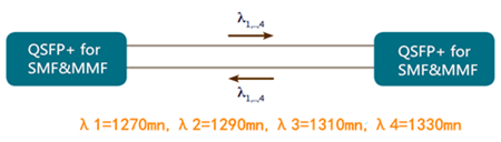
It’s know that a fiber optic transceiver may either operate on single-mode fiber (SMF) or multi-mode fiber (MMF). However, this SMF&MMF 40G QSFP+ transceiver is able to communicate with both SMF and MMF, without the need for any software/hardware changes to the transceiver module or any additional hardware in the network. It has 4 channels (1270, 1290,1310, and 1330nm) of 10G multiplexed inside the module to transmit and receive an aggregate 40G signal over 2 strands of fiber with a duplex LC connector.
Based on IEEE defined 40GBASE-LR4 specifications, this supports distances up to 150m over OM3 or OM4 MMF and up to 500m over SMF. Certainly, different fiber optic equipment vendors may have different specifications.
SMF&MMF 40G QSFP+ Transceiver Advantages
SMF&MMF 40G QSFP+ transceiver is designed for seamless migrations from existing 10GbE to 40GbE networking without modification or expansion of the fiber network. It addresses several challenges faced by today’s data centers and the passages highlight the advantages of this transceiver.
No Redesign or Expansion of Fiber Network
Other short-reach 40G QSFP+ transceiver types, such as MMF 40GBASE-SR4 transceivers (100m over OM3 MMF), utilize four independent 10G transmitters and receivers for an aggregate 40G link. These 40GBASE-SR4 transceivers (eg. JG325B) use a MPO-12 connector and require 8-fiber parallel OM3 or OM4. As a result, customers installing MTP/MPO fiber systems may need to deploy new fiber while upgrading from 10G to 40G. However, SMF&MMF 40G QSFP+ transceiver uses duplex LC connector, which is consistent with the existing 10G connections. It works on existing OM3 and OM4 MMF infrastructure which is widely installed and used for 10GbE networks, thus free from redesign or expansion of the fiber network.

Increase in the Number of 40G Links
The existing MMF 40GbE solutions use of 8 fibers for a 40G link, and customers have to add additional fiber if they want to increase the number of 40G links. But if you deploy SMF&MMF 40G QSFP+ transceiver, the number of 40G links is 4our times of that existing MMF 40GbE solutions without any changes to their fiber infrastructure. During this link increase, the network scale and performance are also expanded.
A Cost-effective Solution for SMF Infrastructure
Limited in the distance reach that multi-mode transceivers can support, the migration from 10G to 40G, to 100G, or even 400G would become simpler with SMF. But single-mode transceivers typically cost up to 4 times more compared to multi-mode transceivers. Since SMF&MMF QSFP+ transceiver interoperates with QSFP-LR4 and QSFP-LR4L optics, it’s a cost effective solution for SM fiber infrastructure for distances up to 500m. And customers can deploy mixed connections without fiber concerns.
Simplification in Infrastructure Deployment
SMF&MMF QSFP+ transceiver boasts of the unique characteristic of working through both SMF and MMF without any requirement for additional fiber. Customers can consolidate their optics and use SMF&MMF QSFP+ transceiver in their network without concern about the fiber type, which makes the full use of existing cabling infrastructure, leading to the reduced equipment cost and simplification of deployment.
Conclusion
SMF&MMF QSFP+ transceiver allows data centers to migrate from 10GbE to 40GbE without redesigning or modifying the cabling infrastructure, providing companies or organizations a cost-effective solution to expand their fiber network. With SMF&MMF QSFP+ transceiver in hand, a smooth 40GbE migration at low cost is around the corner. Fiberstore SMF&MMF 40G QSFP+ transceivers are supplied to help you achieve smooth 40G migration. Besides, their interoperate QSFP-LR4 and QSFP-LR4L transceivers are also available, such as Cisco QSFP-40G-LR4 and WSP-Q40GLR4L. For more information about SMF&MMF QSFP+ transceivers, you can visit Fiberstore.
Oznake: SMF&MMF 40G QSFP+ transceiver, MMF 40GBASE-SR4, JG325B, 40GBASE-LR4, QSFP-LR4L, WSP-Q40GLR4L
komentiraj (0) * ispiši * #
Cabling Data Center Process: Planning & Implementing its Infrastructure
utorak , 15.03.2016.Today’s data centers are the home to diverse bandwidth-demanding devices, like servers, storage systems, and backup devices which are interconnected by networking equipment. All these devices drive the need for reliable and manageable cabling infrastructure with higher performance and more flexibility for today and future growth. While managing the cabling in data centers, two main processes are included: planning the cabling infrastructure and implementing the cables.
Planning the Cabling Infrastructure
As networking equipment becomes denser, and port counts in data centers increase to several hundred ports, managing cables connected to these devices becomes a difficult challenge. Thus, during planning the cabling infrastructure, it’s wise to do the following:
Choosing Fiber Cable Assembly
This assembly has a single connector at one end of the cable and multiple duplex breakout cables at the other end, an alternative to avoid cable management. The LC (Lucent Connector) -MPO (Multifiber Push-On) breakout cable assemblies are designed to do just that. The idea is to pre-connect the high-density, high- port-count LC equipment with LC-MPO breakout cable to dedicated MPO modules within a dedicated patch panel, reducing equipment cabling clutter and improving cable management. This image below show the LC-MPO breakout cable assembly that consolidates six duplex LC ports into one MPO connection.

Nowadays, this breakout technology is widely used in 40 Gigabit Ethernet (GbE) applications. Like QSFP-4X10G-AOC10M, this product is the QSFP to four SFP+ active optical breakout cable assembly with the 10m short reach.
Using Color to Identify Cables
Color coding simplifies management and can save you hours when you need to trace cables. Cables are available in many colors (table shown below). For instance, multi-mode fiber (MMF) looks in orange (OM1, OM2) and in aqua (OM3), while yellow is usually the color of single-mode fiber (SMF) which is taken as the transmission media when the required distance is as long as 2km, or 10km . Take WSP-Q40GLR4L for example, this 40GBASE-LR4L QSFP+ transceiver works through SMF for 2km link length.

Implementing the Cabling Infrastructure
While implementing the cables, the following tasks should be obeyed by.
Testing the Links
Testing cables throughout the installation stage is imperative. Any cables that are relocated or terminated after testing should be retested. Although testing is usually carried out by an authorized cabling implementer, you should obtain a test report for each cable installed as part of the implementation task.
Building a Common Framework for the Racks
this step is to stage a layout that can be mirrored across all racks in data centers for consistency, management, and convenience. Starting with an empty 4-post rack or two, build out and establish an internal standard for placing patch panels, horizontal cable managers, vertical cable managers, and any other devices that are planned for placement into racks or a group of racks. The INTENTION is to fully cable up the common components while monitoring the cooling, power, equipment access, and growth for the main components in the racks.
A good layout discourages cabling in between racks due to lack of available data ports or power supply ports, allowing more power outlets and network ports than you need. This will save you money in the long run as rack density increases, calling for more power and network connectivity. Using correct length cables, route patch cables up or down through horizontal patch panels alleviates overlapping other ports. Some cable slack may be needed to enable easy removal of racked equipment.
Documentation
Typically, the most critical task in cable management is to document the complete infrastructure: including diagrams, cable types, patching information, and cable counts. It’s advised update the documentation and keep it accessible to data center staff on a share drive or intranet Web site.
Stocking Spare Cables
It’s suggestible to maintain an approximately the same amount on the installed cabling and ports in use, so as to face the environment variation or emergency.
Conclusion
Understanding the above-mentioned information about cabling planning and implementation helps you to have a scalable, dependable and manageable cabling infrastructure in data centers. Fiberstore offers many cable management tools, including fiber termination box, cable ties, and distribution cabinet. For more information about cable management solutions, you can visit Fiberstore.
Originally published at www.fiber-optic-components.com/cabling-data-center-process-planning-implementing-its-infrastructure.html
Oznake: cabling infrastructure, breakout cable assembly, QSFP-4X10G-AOC10M, Color coding, WSP-Q40GLR4L, SMF, MMF, cable management tools
komentiraj (1) * ispiši * #
