Four Aspects About Multi-mode Fibers
petak , 20.05.2016.Data centers are never ceased their steps to bring greater speed and efficiency to telecommunication and datacoms industries. An enormous amount of data is transmitted, gathered and analyzed everyday, all which requires a vast number of high-bandwidth interconnections between data centers, and people. During these interconnections, fiber optic cables see their heaviest use.
Fiber optic cables can deliver more bandwidth for voice, video and data applications, and carry thousands of times more information than copper wire. With fiber optic cables, reliable and secure data transmission is ensured. Fiber optic cables are available in single-mode and multi-mode versions based on transmission mode standard. This article puts its focus on the latter version: multi-mode fiber (MMF), discussing MMF from its core size attenuation, bandwidth and manufacturing ways.
MMF: Larger Core Size
It’s known that MMF has a much larger core size and cladding diameter, whose different types are distinguished by jacket color: for 62.5/125 µm (OM1) and 50/125 µm (OM2), orange jackets are recommended, while aqua is recommended for 50/125 µm "laser optimized" OM3 and OM4. MMF’s larger core endows it greater light gathering capacity, allowing multiple modes of light to propagate through the fiber simultaneously. Thus, MMF is more suitable for relatively shorter-reach application, usually less than 600m. When it’s deployed in GbE applications, the maximum reach is 550m in combination of 1000BASE-SX SFP (ie. 1783-SFP1GSX).
MMF: Attenuation/Signal Loss
Attenuation refers to the reduction of signal loss when light travels through the fiber optic cable, which is measured in decibels per kilometer (db/km). Insertion loss is the total attenuation from all sources plus any reflection losses over a specific fiber length. Such attenuation is often caused by absorption of optical energy by tiny impurities in the fiber such as iron, copper, or cobalt. Sometimes, the scattering of the light beam as it hits microscopic imperfections, called Rayleigh scattering can also lead to signal loss phenomenon. Attenuation problem is a commonplace in MMFs.
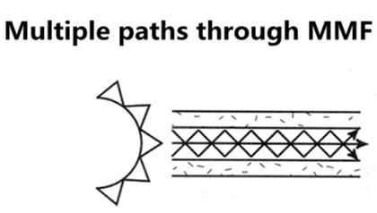
MMF: More Bandwidth
Bandwidth quantifies the complicated data-carrying capacity of MMF, given in units of megahertz-kilometer (MHz·km). Bandwidth behavior of MMF arises from multi-modal dispersion (multi-path signal spreading) which happens as the result of light traveling along different modes in the core of fibers. The bandwidth specification of performance of a MMF is verified through optical measurements during fiber manufacture. Actual system performance and data-rate handling rely heavily on bandwidth, affected by transceiver technology and device characteristics.
MMF: Manufacturing Ways
MMF can be manufactured in two ways: step-index or graded index.
Step-index fiber has an abrupt change or step between the index of refraction of the core and the index of refraction of the cladding. Multi-mode step-index fibers have lower bandwidth than other fiber designs.
Graded index fiber is designed to reduce modal dispersion inherent in step index fiber. This design maximizes bandwidth while maintaining a larger core diameter for simplified system assembly, connectivity and lower network costs. Graded index fiber is made up of multiple layers with the highest index of refraction at the core. Each succeeding layer has a gradually decreasing index of refraction as the layers move away from the center. High order modes enter the outer layers of the cladding and are reflected back towards the core. Multi-mode graded index fibers have less attenuation (loss) of the output pulse and have higher bandwidth than multi-mode step-index fibers.
MMF related transceivers: Multi-mode Transceivers
A fiber optic transceiver is a package, usually a pluggable module, comprising of a receiver on one end of the fiber and a transmitter on the other end. Over the years, multi-mode bandwidth specifications and measurement methods have evolved along with the transceiver technology, so as to keep up with delivery of higher transmission speeds. The combination of transceiver and fiber optic cable plays an important role in fiber’s practical link length. As for multi-mode transceivers which have larger core, they are often used in short-reach applications with 850mn wavelength. Listed below are several commonly-used multi-mode transceiver ports: 1000BASE-SX, 10GBASE-SR, 10GBASE-LRM, among which 10GBASE-SR port type enjoys widely deployment in 10GbE applications when the required distance is not so long. Take F5-UPG-SFP+-R for example, this F5 compatible 10GBASE-SR SFP+ transceiver listed in Fiberstore takes OM3 MMF as its transmission medium for 300m reach.

Besides what have been discussed above, there is also another MMF feature that comes into your mind: that is the affordability. MMF is less expensive than its counterpart single-mode fiber (SMF). Because of this, more people prefer MMF to SMF when the required distance is not so long. Thus, this big saving can be re-invented in other projects.
Conclusion
MMF is able to operate at data rates from 100Mbit/s to 1Gbit/s, to 10Gbit/s, to 40Gbit/s, to100Gbit/s, or even more. Choosing the right fiber type for your network project is a critical task. Here, Fiberstore MMFs provide the cost-effective combination of leading bandwidth performance and increased reliability, suitable for the demanding bandwidth interconnects. You can visit Fiberstore directly for more information about MMFs.
Oznake: MMF, Multi-mode Transceivers, 1000BASE-SX, 1783-SFP1GSX, 10GBASE SR, F5-UPG-SFP+-R
komentiraj (0) * ispiši * #
Why Choose 10 Gigabit Ethernet?
srijeda , 13.04.2016.Since Ethernet technology came into people's use in 1970s, Gigabit Ethernet (GbE) has long deminated the local area network (LAN) applications. But when to connect servers to storage area networks (SANs) and network attached storage (NAS) or for server-to-server connections, GbE seems to be not sufficient enough. In such a case, Ethernet has developed the later technology standard as newer, higher performing iteration—10GbE.
The Institute of Electrical and Electronics Engineers (IEEE) 802.3 working group has published several standards regarding 10GbE, including 802.3ae-2002 (fiber -SR, -LR, -ER), 802.3ak-2004 (CX4 copper twin-ax InfiniBand type cable), etc. Among these standard interfaces, 10GBASE-SR is the most-widely used type, like Cisco SFP-10G-SR and Cisco SFP-10G-SR-S. With 10Gigabit connectivity becoming widely available, 10GbE technology has emerged as the connection choice for many companies to grow their networks and support new applications and traffic types. Behind the 10GbE, there are three main advantages which explain why users choose it today.

Data Center Network Simplification
While Fibre Channel and InfiniBand are specialized technologies that can connect servers and storage, they can’t extend beyond the data center. However, a single 10GbE network and a single switch can support the LAN, server-to-server communications, and can connect to the wide-area network. Ethernet and IP network technology are familiar to network designers, so replacing multiple networks with a single 10GbE network avoids complex staff training. And by consolidating multiple gigabit ports into a single 10gigabit connection, 10GbE simplifies the network infrastructure while providing greater bandwidth.
Traffic Prioritization and Control
A major advantage of 10GbE is that separate networks for SANs, server-to-server communication and the LAN can be replaced with a single 10GbE network. While 10Gb links may have sufficient bandwidth to carry all three types of data, bursts of traffic can overwhelm a switch or endpoint.
SAN performance is extremely sensitive to delay. Slowing down access to storage has an impact on server and application performance. Server-to-server traffic also suffers from delays, while LAN traffic is less sensitive. There must be a mechanism to allocate priority to critical traffic while lower-priority data waits until the link is available.
Existing Ethernet protocols do not provide the controls needed. A receiving node can send an 802.3x PAUSE command to stop the flow of packets, but PAUSE stops all packets. 802.1p was developed in the 1990s to provide a method to classify packets into one of eight priority levels. However, it did not include a mechanism to pause individual levels. The IEEE is now developing 802.1Qbb Priority-based Flow Control (PFC) to provide a way to stop the flow of low-priority packets while permitting high-priority data to flow.
A bandwidth allocation mechanism is also required. 802.1Qaz Enhanced Transmission Selection (ETS) provides a way to group one or more 802.1p priorities into a priority group. All of the priority levels within a group should require the same level of service. Each priority group is then assigned a percentage allocation of the link. One special priority group is never limited and can override all other allocations and consume the entire bandwidth of the link. During periods when high-priority groups are not using their allocated bandwidth, lower-priority groups are allowed to use the available bandwidth.
Congestion control
802.1Qbb and 802.1Qaz by themselves don't solve the packet loss problem. They can pause low-priority traffic on a link, but they don't prevent congestion when a switch or an end node is being overwhelmed by high-priority packets from two or more links. There must be a way for receiving nodes to notify sending nodes to slow their rate of transmission.
IEEE 802.1Qau provides such a mechanism. When a receiving node detects that it is nearing the point where it will begin discarding incoming packets, it sends a message to all nodes currently sending to it. Sending nodes slow their transmission rate. Then, when congestion is cleared, the node sends a message informing senders to resume their full rate.
10GbE in Data Centers
For many institutions, especially those that utilize automated trading, uptime and response time is critical. Longer delays than a second can be exceedingly costly. With servers now being able to transmit bandwidth and network downtime, today’s data centers of some companies need extended bandwidth. 10GbE is an ideal technology to move large amounts of data quickly. The bandwidth it provides in conjunction with server consolidation is highly advantageous for Web caching, real-time application response, parallel processing and storage.
Conclusion
10GbE comes as the ideal connection choice for some companies, delivering greater bandwidth for sending data over Ethernet architectures with reduced cost and complexity. Fiberstore offers an ocean of 10GbE solutions, such as high-quality SFP+ modules (eg. Cisco SFP-10G-SR and SFP-10G-SR-S mentioned above). For more information about 10GbE equipment, you can visit Fiberstore or directly connect me at Linkedin @Fern Xu (Fiberstore).
Oznake: 10GbE, 10GBASE SR, Cisco SFP-10G-SR, Cisco SFP-10G-SR-S, SFP+ modules
komentiraj (0) * ispiši * #
