Four Aspects About Multi-mode Fibers
petak , 20.05.2016.Data centers are never ceased their steps to bring greater speed and efficiency to telecommunication and datacoms industries. An enormous amount of data is transmitted, gathered and analyzed everyday, all which requires a vast number of high-bandwidth interconnections between data centers, and people. During these interconnections, fiber optic cables see their heaviest use.
Fiber optic cables can deliver more bandwidth for voice, video and data applications, and carry thousands of times more information than copper wire. With fiber optic cables, reliable and secure data transmission is ensured. Fiber optic cables are available in single-mode and multi-mode versions based on transmission mode standard. This article puts its focus on the latter version: multi-mode fiber (MMF), discussing MMF from its core size attenuation, bandwidth and manufacturing ways.
MMF: Larger Core Size
It’s known that MMF has a much larger core size and cladding diameter, whose different types are distinguished by jacket color: for 62.5/125 µm (OM1) and 50/125 µm (OM2), orange jackets are recommended, while aqua is recommended for 50/125 µm "laser optimized" OM3 and OM4. MMF’s larger core endows it greater light gathering capacity, allowing multiple modes of light to propagate through the fiber simultaneously. Thus, MMF is more suitable for relatively shorter-reach application, usually less than 600m. When it’s deployed in GbE applications, the maximum reach is 550m in combination of 1000BASE-SX SFP (ie. 1783-SFP1GSX).
MMF: Attenuation/Signal Loss
Attenuation refers to the reduction of signal loss when light travels through the fiber optic cable, which is measured in decibels per kilometer (db/km). Insertion loss is the total attenuation from all sources plus any reflection losses over a specific fiber length. Such attenuation is often caused by absorption of optical energy by tiny impurities in the fiber such as iron, copper, or cobalt. Sometimes, the scattering of the light beam as it hits microscopic imperfections, called Rayleigh scattering can also lead to signal loss phenomenon. Attenuation problem is a commonplace in MMFs.
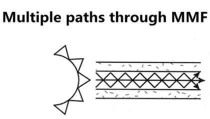
MMF: More Bandwidth
Bandwidth quantifies the complicated data-carrying capacity of MMF, given in units of megahertz-kilometer (MHz·km). Bandwidth behavior of MMF arises from multi-modal dispersion (multi-path signal spreading) which happens as the result of light traveling along different modes in the core of fibers. The bandwidth specification of performance of a MMF is verified through optical measurements during fiber manufacture. Actual system performance and data-rate handling rely heavily on bandwidth, affected by transceiver technology and device characteristics.
MMF: Manufacturing Ways
MMF can be manufactured in two ways: step-index or graded index.
Step-index fiber has an abrupt change or step between the index of refraction of the core and the index of refraction of the cladding. Multi-mode step-index fibers have lower bandwidth than other fiber designs.
Graded index fiber is designed to reduce modal dispersion inherent in step index fiber. This design maximizes bandwidth while maintaining a larger core diameter for simplified system assembly, connectivity and lower network costs. Graded index fiber is made up of multiple layers with the highest index of refraction at the core. Each succeeding layer has a gradually decreasing index of refraction as the layers move away from the center. High order modes enter the outer layers of the cladding and are reflected back towards the core. Multi-mode graded index fibers have less attenuation (loss) of the output pulse and have higher bandwidth than multi-mode step-index fibers.
MMF related transceivers: Multi-mode Transceivers
A fiber optic transceiver is a package, usually a pluggable module, comprising of a receiver on one end of the fiber and a transmitter on the other end. Over the years, multi-mode bandwidth specifications and measurement methods have evolved along with the transceiver technology, so as to keep up with delivery of higher transmission speeds. The combination of transceiver and fiber optic cable plays an important role in fiber’s practical link length. As for multi-mode transceivers which have larger core, they are often used in short-reach applications with 850mn wavelength. Listed below are several commonly-used multi-mode transceiver ports: 1000BASE-SX, 10GBASE-SR, 10GBASE-LRM, among which 10GBASE-SR port type enjoys widely deployment in 10GbE applications when the required distance is not so long. Take F5-UPG-SFP+-R for example, this F5 compatible 10GBASE-SR SFP+ transceiver listed in Fiberstore takes OM3 MMF as its transmission medium for 300m reach.

Besides what have been discussed above, there is also another MMF feature that comes into your mind: that is the affordability. MMF is less expensive than its counterpart single-mode fiber (SMF). Because of this, more people prefer MMF to SMF when the required distance is not so long. Thus, this big saving can be re-invented in other projects.
Conclusion
MMF is able to operate at data rates from 100Mbit/s to 1Gbit/s, to 10Gbit/s, to 40Gbit/s, to100Gbit/s, or even more. Choosing the right fiber type for your network project is a critical task. Here, Fiberstore MMFs provide the cost-effective combination of leading bandwidth performance and increased reliability, suitable for the demanding bandwidth interconnects. You can visit Fiberstore directly for more information about MMFs.
Oznake: MMF, Multi-mode Transceivers, 1000BASE-SX, 1783-SFP1GSX, 10GBASE SR, F5-UPG-SFP+-R
komentiraj (0) * ispiši * #
Why Choose 10GBASE-T Interface for 10GbE Infrastructure?
četvrtak , 10.03.2016.The increasing availability of virtualization applications and unified networking infrastructure puts extreme input/output (I/O) demands on 1 Gigabit Ethernet (GbE), making data centers facing bandwidth challenges. Deploying 10GbE infrastructure can address these problems by delivering greater bandwidth, simplifying network, and lowering power consumption.
Well, the deployment of 10GbE requires cost-effective solution. In general, there are several 10GbE interfaces to choose from, including CX4, SFP+ fiber, SFP+ Direct Attach Copper (DAC), and 10GBASE-T. As for CX4, it’s an older technology that does not meet high density requirements. Although most deployment chooses SFP+ fiber (eg. F5-UPG-SFP+-R) solution, fiber is in no case cost-effective. Besides, SFP+ DAC is limited by its short reach. In such a case, 10GBASE-T is selected as the less power-consuming and cost-saving solution for 10GbE. This article details at what are the reasons that drive the 10GBASE-T to become the suitable 10GbE media option.
Firstly, let’s figure out what is 10GBASE-T. 10GBASE-T, or IEEE 802.3an-2006, is a standard released in 2006 to provide 10Gbit/s connections over unshielded or shielded twisted pair cables, with distances up to 100 meters (330 ft) with RJ45 connectors. 10GBASE-T cable infrastructure can also be used for 1000BASE-T, allowing a gradual upgrade from 1000BASE-T using auto-negotiation to select which speed to use.

Listed below are several reasons why 10GBASE-T become the 10GbE media option.
Flexibility in Reach
Like other copper network implementations using BASE-T standards, 10GBASE-T works for link lengths up to 100 meters, giving network designers a far greater level of flexibility in connecting devices in the data center. Able to realize flexible reach, 10GBASE-T can accommodate either top of the rack, middle of row, or end of the row network topologies, making server placement even more easy and convenient.
Backward Compatibility
10GBASE-T is backward-compatible with existing 1GbE networks, meaning that it can be deployed based on existing 1GbE switch infrastructures in data centers that are cabled with CAT6 and CAT6A (or above) cabling. In other words, when migrating from 1GbE to 10GbE, 10GBASE-T provides an easy path, saving cost.
Reduction in Power Consumption
In widespread deployment of 10GbE networks using 10GBASE-T interface, one challenge lies in the fact that the early physical layer interface chips (PHYs) consumed too much power. The original gigabit chips were roughly 6.5 Watts per port. With technology improvements, the chips improved from one generation to the next, leading to less 1 W per port for 1GbE interfaces. It’s the same with 10GBASET. And owing to the manufacturing processes, the 10GBASE-T reduction in power consumption has been made possible. The figure below shows the relationship between power consumption and wavelength.

When 10GBASE-T adapters were first introduced in 2008, they required 25 W of power for a single port, and later, power has been reduced thanks to the successive generations of developing newer and smaller process technologies. The latest 10GBASE-T adapters require less than 6 W per port,which makes 10GBASE-T suitable for motherboard integration and high-density switches.
Latency
Depending on packet size, latency for 10GBASE-T ranges from just over 2 µs to less than 4 µs—a much tighter latency range. For Ethernet packet sizes of 512 bytes or larger, 10GBASE-T’s overall throughput offers an advantage over 1000BASE-T. Latency for 10GBASE-T is more than three times lower than 1000BASE-T with larger packet sizes. For those enterprise applications that have been operating for years with 1000BASE-T latency, 10GBASE-T latency only makes things better. Many products designed for Local Area Network (LAN) purposely add small amounts of latency to reduce power consumption or CPU overhead.
Broad use of 10GBASE-T interface simplifies data center infrastructures, making it easier to manage server connectivity while delivering the bandwidth needed for heavily virtualized servers and I/O-intensive applications. As the cost continues to fall, and new technological processes further lower power consumption, all these make 10GBASE-T suitable for integration on server motherboards.
Conclusion
10GBASE-T offers the flexible reach, and its backward compatibility with existing 1GbE networks makes it the ideal cost-effective media option for 10GbE infrastructure. As a professional fiber optic product manufacturer and supplier, Fiberstore provides countless 10GBASE-T transceivers for 10GbE applications. Of course, besides 10GBASE-T, other 10GBASE standard transceivers also available in Fiberstore, such as 10GBASE-ER SFP+ (J9153A). For more information about 10GbE interfaces, you can visit Fiberstore.
Originally published at www.fiber-optic-components.com/why-choose-10gbase-t-interface-for-10gbe-infrastructure.html
Oznake: CX4, SFP+ fiber, F5-UPG-SFP+-R, SFP+ DAC, 10Gbase-T, 10GBASE-ER SFP+, J9153A
komentiraj (0) * ispiši * #
