Fiber Optic Cable Basics: Construction & Certification Measurements
srijeda , 11.05.2016.Being one of the most popular and cost-effective means for communications, fiber optic cables have been installed in the backbone for years, as fiber makes communications at the speed of light possible. And their greater bandwidth and lower attenuation allow for longer distances and more channels compared with copper wires. The number of articles and papers on fiber optic cables is so large. Some are about their classifications (tight buffer/distribution/breakout/loose tube), some are on their advantage discussion (speed, distance, security), and others are meant to touch upon their related connector color codes (orange, yellow, blue). While in this article, still some basic information is included, like the construction and certification measurements.
Fiber Optic Cable Construction
Fiber optic cable construction includes a core, cladding, coating, strengthening fibers, and a cable jacket.
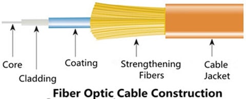
Fiber Core
Fiber core refers to the light-carrying element at the center of the cable, transmitting optical data signals from an attached light source to a receiving device. The core is a single continuous strand of extruded silica glass or plastic that’s measured in microns (µm) by the size of its outer diameter. The larger the core, the more light the cable can carry. The two most common multi-mode sizes are 50 and 62.5 microns. Single-mode cores are 8.5–9 microns.
The cores of OM1 and OM2 multi-mode fiber (MMF) are made differently than the cores of laser-optimized OM3 and OM4 cable. OM1 and OM2 have a small defect in the core called an index depression. This enables them to be used with LED light sources. In contrast, OM3 and OM4 are manufactured without the center defect, which enables them to be used directly with VCSELS for greater speeds and distance. These OM3 and OM4 MMFs are widely used in Gigabit applications, especially in 10GbE transmission when they are used as the medium for 10GbE transceiver modules (ie. SFP-10G-SR).
Cladding
The optic cladding surrounds the fiber core. It functions as a boundary that contains the light waves and causes the internal refraction, enabling light to travel through the length of the fiber segment.
Coating
There is a protective acrylate coating that surrounds the core and cladding to protect them. This coating keeps the glass from dust and scratches that can affect fiber strength.
Strengthening Fibers
These components are to protect the core against crushing forces and excessive tension during cable handling, especially the installation and termination process. The materials can range from aramid yarn to wire strands to gel-filled sleeves.
Cable jacket
Fiber optic cable jacket is available in PVC and plenum-rated versions. The former type is typically used for patch connections in the data center, wiring closet, and at the desktop, while the latter kind is deployed when you need to route a cable through the buildings air plenum. Plenum cable has a flame-resistant jacket to inhibit the spread of fire.
Performance Measurements
Unlike copper cable, it’s easier to certify fiber optic cable, since it’s immune to electrical interference. When certify it, the following measurements are necessary.
Attenuation/Decibel Loss
Attenuation means the decrease of signal strength as it travels through the fiber optic cable, measured in decibels/kilometer (dB/km). Generally speaking, attenuation problems are more common to MMF.
Return Loss
This loss refers to the amount of light that is reflected from the far end of the cable back to the source. The lower the number, the better. For example, a reading of -60 decibels is better than -20 decibels. Like attenuation, return loss is usually greater with MMF.
Graded Refractive Index
This concept measures how the light is sent down the fiber, commonly mensurated at wavelengths of 850 and 1300nanometers. Compared to other operating frequencies, these two ranges yield the lowest intrinsic power loss (This is valid for MMF only.)
Propagation Delay
This is the time a signal takes to travel from one point to another over a transmission channel.
Optical Time-domain Reflectometry (OTDR)
This enables you to isolate cable faults by transmitting high-frequency pulses onto a cable and examining their reflections along the cable. With OTDR, you can also determine the length of a fiber optic cable because the OTDR value includes the distance the optic signal travels.
Notes on Fiber’s Speed & Modal Bandwidth
After introducing basic information about fiber optic cable, here, I’d like to mention two commonly-seen concepts: the first one, fiber’s speed which is not meaning the speed of the signal in the fiber, but the bandwidth potential of the fiber.
The second one, modal bandwidth which is caused by the fact that light in MMF travels in rays or "modes" that take different times to get to through the fiber, thus dispersion occurs. The longer the fiber, the greater the effect. This is the incentive driving fiber manufacturers to develop better MMFs.
Conclusion
Fiber optic cables are suitable for backbone, horizontal, and desktop applications, providing extremely reliable data transmission. They are less susceptible to temperature fluctuations, and can even be submerged in water or under sea. Fiberstore fiber optic cables come in various types with detailed specifications displayed for your convenient choice. These quality cables are designed with best-in-class performance. Besides, you can also find Push-Pull MPO cable, a kind of fiber patch cable with push-pull MPO connector here. For more information about fiber optic cables or patch cords, you can visit Fiberstore.
Oznake: fiber optic cables, MMF, 10GbE transmission, SFP-10G-SR, patch cords, Push-Pull MPO cable
komentiraj (0) * ispiši * #
Considerations About Fiber Optic Transceiver Designing
utorak , 22.03.2016.The rapid expansion of fiber optic networks, including data services measured by data volume or bandwidth, shows that fiber optic transmission technology is and will continue to be a significant part of future networking systems. Network designers are becoming increasingly comfortable with fiber solutions, since the use of which allows for more flexible network architecture and other advantages, such as EMI (Electromagnetic Interference) resilience and data security. Fiber optic transceivers play an really important role in these fiber connections. And while designing fiber optic transceivers, three aspects need to be considered: environmental situation, electrical condition and optical performance.
What Is a Fiber Optic Transceiver?
The fiber optic transceiver is a self-contained component that transmits and receives signals. Usually, it is inserted in devices such as routers or network interface cards which provide one or more transceiver module slot. The transmitter takes an electrical input and converts it to an optical output from a laser diode or LED. The light from the transmitter is coupled into the fiber with a connector and is transmitted through the fiber optic cable plant. Then the light from the end of the fiber is coupled to a receiver where a detector converts the light into an electrical signal which is then conditioned properly for use by the receiving equipment. There are a full range of optical transceivers available in telecommunication market, like SFP transceiver, SFP+ transceiver (eg. SFP-10G-SR shown below), 40G QSFP+, 100G CFP, etc.

Designing Considerations
It’s true that fiber links can handle higher data rates over longer distances than copper solutions, which drive the even wider use of fiber optic transceivers. While designing fiber optic transceivers, the following aspects should be taken into consideration.
Environmental Situation
One challenge comes to the outside weather—especially severe weather at elevated or exposed heights. The components must operate over extreme environmental conditions, over a wider temperature range. The second environmental issue related to the fiber optic transceiver design is the host board environment which contains the system power dissipation and thermal dissipation characteristics.
A major advantage of the fiber optic transceiver is the relatively low electrical power requirements. However, this low power does not exactly mean that the thermal design can be ignored when assembling a host configuration. Sufficient ventilation or airflow should be included to help dissipate thermal energy that is drawn off the module. Part of this requirement is addressed by the standardized SFP cage which is mounted on the host board and also serves as a conduit for thermal energy. Case temperature reported by the Digital Monitor Interface (DMI), when the host operates at its maximum design temperature, is the ultimate test of the effectiveness of the overall system thermal design.
Electrical Condition
Essentially, the fiber transceiver is an electrical device. In order to maintain error free performance for the data passing through the module, the power supply to the module must be stable and noise-free. What’s more, the power supply driving the transceiver must be appropriately filtered. The typical filters have been specified in the Multisource Agreements (MSAs) which have guided the original designs for these transceivers. One such design in the SFF-8431 specification is shown below.

Optical Performance
Optical performance is measured as Bit Error Rate, or BER. The problem facing designing optical transceiver lie in the case that the optical parameters for the transmitter and receiver have to be controlled, so that any possible degradation of the optical signal while traveling along the fibers will not cause poor BER performance. The primary parameter of relevance is the BER of the complete link. That is, the start of the link is the source of the electrical signals which drive the transmitter, and at the end, the electrical signal is received and interpreted by the circuitry in the host by the receiver. For those communication links which use optical transceivers, the primary goal is to guarantee BER performance at different link distances, and to ensure broad interoperability with third party transceivers from different vendors.
Conclusion
Fiber technology is becoming maturer, leading to the wider use of fiber optic transceivers. With the three aspects mentioned above in mind, designing fiber optic transceivers should be easier. Fiberstore supplies many transceivers which are fully compatible with major brands, including HP compatible transceivers (eg. J4858C). For more information about fiber optic transceivers, you can visit Fiberstore.
Oznake: fiber optic transceiver, SFP, SFP-10G-SR, compatible transceivers, J4858C
komentiraj (0) * ispiši * #
