Three Useful Fiber Patch Cords and Their Use
petak , 27.05.2016.With the rapid advancement of fiber optic technology and trend towards optical communications, fiber optic patch cord has realized its great use in high speed data transmission networks, found in routers, fiber patch panels, media converters and even in hubs and switches. Compared to its previous counterpart, fiber optic jumper causes lower signal loss, delivers more bandwidth and carries more information, becoming more and more popular in cabling installation or upgrading between or inside buildings. Just like the transceiver modules which fall in many types based on different standards, fiber optic patch cables are also available in several kinds, including single-mode/multi-mode, simplex/duplex, MPO/MTP cable, armored patch cord, and so on. This article aims to introduce the last three useful fiber patch cords and their use.
Simplex/Duplex Patch Cables
Simplex cable, also known as single strand cables, has one fiber, tight-buffered (coated with a 900micron buffer over the primary buffer coating) with Kevlar (aramid fiber) strength members and jacketed for indoor use. The jacket is usually 3mm (1/8 in.) diameter, but some 2mm cable is sometimes used with small form factor connectors. Duplex (zipcord) cable has two fibers joined with a thin web.
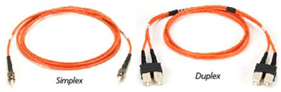
Since simplex patch cord consists of only one fiber link, it’s used in such applications that only require one-way data transfer. But when the equipment can transmit and receive on two different wavelengths, simplex cable can also be considered. For example, transmit could be at 1310nm and receive could be at 1550nm. This application is found more with single-mode simplex patch cable.
Duplex patch cable is suitable for applications that require simultaneous, bidirectional data transfer. Typical applications include workstations, fiber switches and servers, Ethernet switches, backbone ports, and similar hardware.
MPO/MTP Cable
MPO/MTP cable uses multi-fiber MPO/MTP connectors for setting up high-performance data networks in data centers, so as to achieve greater bandwidth and handle network traffic requirements. Specifically, in MPO/MTP cable component, each one of the connector are used with ribbon type fiber optic cables which contain multi-fiber in one single jacket, so that MPO/MTP patch cord greatly saves space, very convenient to use. Based on single ferrule MT technology, the MPO/MTP cable assemblies are able to provide up to 72 fiber connections in a single point, reducing the physical space and labor requirement, while providing the same bandwidth capacity of a multi-fiber cable with individual fiber connector terminations per cable. MTP cables can be divided into trunk and harness versions (image below).
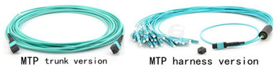
MPO/MTP patch cables have great use in Gigabit applications, especially in 40GbE. Often, MPO/MTP connectors terminate OM3 or MO4 to form structured cabling, serving as the transmission medium for 40GBASE optics (ie. QFX-QSFP-40G-SR4).
Armored Patch Cord
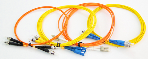
Armored patch cord enjoys all the features of standard fiber patch cord, available in single-mode and multi-mode version (shown below), except its much stronger characteristic. It won’t get damaged even it is stepped by an adult. What’s more, this kind of patch cord is anti-rodents, and when it’s utilized, people do not need to worry that the rodent animals like the rats may bite the cables and make them broken. Although armored fiber cables are strong, they are actually as flexible as standard fiber jumper cords, and they can be bent randomly without being broken.
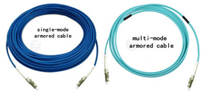
Armored patch cable can be made with the similar outer diameter to the standard patch cable, which makes it a space-saving design. In addition, armored fiber cables can be with different jacket colors and jacket types, like OFNR. Light in weight, armored fiber patch cords can be with SC, ST, FC, LC, MU, SC/APC, ST/APC, FC/APC, LC/APC types of terminations.
The armored fiber optic patch cords are more robust designed, suitable to be deployed in FTTH projects inside the buildings. They use stainless steel armor inside the jacket to be resistant of high tension and pressure, able to resist the weight of an adult person.
Conclusion
Fiber optic patch cables are of great use in various conditions from local area network to airplanes, especially in communication networks in which the importance of patch cords is even more obvious. To get the high-quality patch cords, you can choose Fiberstore, which supplies a wide range of cables, including simplex/duplex, MPO/MTP cable, armored patch cord discussed in this text. Other cable types, such as push-pull patch cords, and 10G SFP+ DAC cable, are also available. If you would like to buy such a product, you can visit Fiberstore directly.
Oznake: fiber optic patch cord, fiber optic jumper, simplex/duplex, MPO/MTP cable, armored patch cord, push-pull patch cords, DAC cable
komentiraj (0) * ispiši * #
Copper & Optical SFP Modules
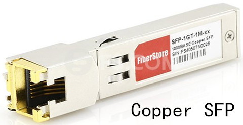
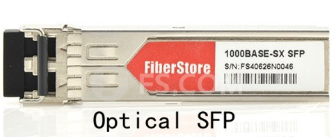
srijeda , 25.05.2016.In order to maintain the configuration flexibility and establish connections that allow smooth data transfer from the source to the end point, SFP transceiver modules are utilized in the copper or optical Gigabit Ethernet (GbE) networks. SFP (Small Form-factor Pluggable) is a compact, hot-swappable, input/output device used in data communication and telecommunications networks. SFP interfaces between communication devices like switches, routers and fiber optic cables, performing optical and electrical signal conversion. There are many copper an optical SFP transceivers based on different GbE physical layers, such as Cisco 1000BASE-T SFP-GE-T and 1000BASE-SX SFP MGBSX1.
GbE Development
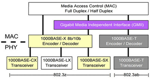
The initial standard for GbE was produced by the IEEE in June 1998 as IEEE 802.3z. Two designs were ratified in IEEE 802.3z to transmit signals over optical cables: the 1000BASE-SX uses short-wavelength laser (850nm) on multi-mode fiber (MMF), and the 1000BASE-LX uses long-wavelength laser (1310nm) on the standard single-mode fiber (SMF). At that time, transmitting 1000Mbps signals on the widely deployed Category 5 UTP was a significant challenge for silicon-chip designers. It requires tremendous signal processing to mitigate the channel impairments in copper wires such as ISI (intersymbol interference) introduced by limited channel bandwidth and signal crosstalks between pairs of copper wires. It was not until a year later that the 1000BASE-T standard (IEEE 802.3ab) was finished. To keep the cost of GbE low, the IEEE 802.3z committee very conservatively defined the transmission distance limit of 1000BASE-SX as 300m, and that of 1000BASE-LX as 5 km.
SFP Port Types
Specified by the Multisource Agreement (MSA), SFP, also known as a mini gigabit interface converter (GBIC), delivers the similar functions just as what a GBIC does, but designed with a much smaller size. As mentioned above, SFP transceiver has several interfaces which are standardized to work on SMFs and MMFs. Besides, SFP transceivers are also available with copper cable interfaces, like 1000BASE-T. This means that SFP module which is designed primarily for optical fiber communications can also communicate over unshielded twisted pair (UTP) cables. The image below shows different GbE SFP standards.
Copper SFP Modules
The development of copper technology in SFP modules is of great importance in enabling system designers to meet objectives while simplifying their inventory and reducing operating costs. These copper SFP transceivers scale Ethernet 10/100Mbps performance to 1000Mbps. Compared with 1Gbps, 1000BASE-T is 100 times as fast as the standard Ethernet. Additionally, the Full Duplex Repeaters (FDRs), when coupled with 1000BASE-T, offer an easy-to-manage, high-burst rate, and shared-media solution capable of supporting both end users and server farms. Popular copper SFP products, like Cisco SFP-GE-T, are used in Gigabit networks and they are fully compatible with 1000Base-T.
Optical SFP Modules
Both 1000BASE-SX and 1000BASE-LX are standardized for fiber optics. They share the 8B/10B 1000BASE-X PCS line coding. In addition to the transmission media, the only difference between 1000BASE-SX and 1000BASE-LX lies in the physical medium dependent (PMD) layer which defines the laser transmitter and photodetector. The interface between the physical medium attachment (PMA) and PMD layer is simply a serial interface. This made it easy to reuse all the designs between 1000BSAE-SX and 1000BASE-LX except the PMD transceiver.
Modern optical SFP modules support digital diagnostics monitoring (DDM) functions, also known as digital optical monitoring (DOM). This feature gives users the ability to monitor the real-time parameters of SFP, such as optical output power, optical input power, temperature, laser-bias current and transceiver supply voltage. The real-time diagnostic parameters can be monitored to alert the system when the transceiver’s specified operating limits are exceeded and compliance cannot be ensured. What’s more, the DDM function can be used to isolate the particular location of fault in fiber optic network system. Combining the DDM interface status flags, transceiver hard pins and diagnostic parametric monitor data the specific location and cause of a link failure can be pinpointed. Certainly, DDM function also has its role in failure prediction on fiber optic links, which is based on the transceiver parametric performance., including device faults and high error rate conditions.
SFP Module Applications
Apart from GbE, SFP modules can also support other communications standards, including synchronous optical networking (SONET)/synchronous digital hierarchy (SDH), and fiber channel. They allow the transport of fast Ethernet and GbE LAN packets over time-division-multiplexing-based WANs, as well as the transmission of E1/T1 streams over packet-switched networks.
SFP Purchasing Tips
When picking such a SFP module for your network, the first important factor to be considered is the price, especially for those small and medium-sized enterprises who have a tight budget. The other points go to the product compatibility, stability, and reliability. Otherwise, no matter how low the price is, it’s of no use.
Conclusion
Copper and optical SFP modules have proven themselves as the useful devices for the increased bandwidth requirements of users with each passing day. Fiberstore supplies a wide range of SFPs to support both copper and optical interfaces. They are fully compatible with such famous brands as Cisco, Juniper, D-Link (ie. DEM-311GT). Here just lists a few for your reference. For more information about SFP modules, you can visit Fiberstore directly.
Oznake: GbE, SFP, 1000BASE-T, SFP-GE-T, 1000BASE-SX, MGBSX1, DEM-311GT, 1000BASE-LX
komentiraj (0) * ispiši * #
Four Aspects About Multi-mode Fibers
petak , 20.05.2016.Data centers are never ceased their steps to bring greater speed and efficiency to telecommunication and datacoms industries. An enormous amount of data is transmitted, gathered and analyzed everyday, all which requires a vast number of high-bandwidth interconnections between data centers, and people. During these interconnections, fiber optic cables see their heaviest use.
Fiber optic cables can deliver more bandwidth for voice, video and data applications, and carry thousands of times more information than copper wire. With fiber optic cables, reliable and secure data transmission is ensured. Fiber optic cables are available in single-mode and multi-mode versions based on transmission mode standard. This article puts its focus on the latter version: multi-mode fiber (MMF), discussing MMF from its core size attenuation, bandwidth and manufacturing ways.
MMF: Larger Core Size
It’s known that MMF has a much larger core size and cladding diameter, whose different types are distinguished by jacket color: for 62.5/125 µm (OM1) and 50/125 µm (OM2), orange jackets are recommended, while aqua is recommended for 50/125 µm "laser optimized" OM3 and OM4. MMF’s larger core endows it greater light gathering capacity, allowing multiple modes of light to propagate through the fiber simultaneously. Thus, MMF is more suitable for relatively shorter-reach application, usually less than 600m. When it’s deployed in GbE applications, the maximum reach is 550m in combination of 1000BASE-SX SFP (ie. 1783-SFP1GSX).
MMF: Attenuation/Signal Loss
Attenuation refers to the reduction of signal loss when light travels through the fiber optic cable, which is measured in decibels per kilometer (db/km). Insertion loss is the total attenuation from all sources plus any reflection losses over a specific fiber length. Such attenuation is often caused by absorption of optical energy by tiny impurities in the fiber such as iron, copper, or cobalt. Sometimes, the scattering of the light beam as it hits microscopic imperfections, called Rayleigh scattering can also lead to signal loss phenomenon. Attenuation problem is a commonplace in MMFs.
MMF: More Bandwidth
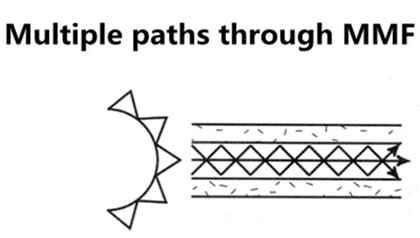
Bandwidth quantifies the complicated data-carrying capacity of MMF, given in units of megahertz-kilometer (MHz·km). Bandwidth behavior of MMF arises from multi-modal dispersion (multi-path signal spreading) which happens as the result of light traveling along different modes in the core of fibers. The bandwidth specification of performance of a MMF is verified through optical measurements during fiber manufacture. Actual system performance and data-rate handling rely heavily on bandwidth, affected by transceiver technology and device characteristics.
MMF: Manufacturing Ways
MMF can be manufactured in two ways: step-index or graded index.
Step-index fiber has an abrupt change or step between the index of refraction of the core and the index of refraction of the cladding. Multi-mode step-index fibers have lower bandwidth than other fiber designs.
Graded index fiber is designed to reduce modal dispersion inherent in step index fiber. This design maximizes bandwidth while maintaining a larger core diameter for simplified system assembly, connectivity and lower network costs. Graded index fiber is made up of multiple layers with the highest index of refraction at the core. Each succeeding layer has a gradually decreasing index of refraction as the layers move away from the center. High order modes enter the outer layers of the cladding and are reflected back towards the core. Multi-mode graded index fibers have less attenuation (loss) of the output pulse and have higher bandwidth than multi-mode step-index fibers.
MMF related transceivers: Multi-mode Transceivers
A fiber optic transceiver is a package, usually a pluggable module, comprising of a receiver on one end of the fiber and a transmitter on the other end. Over the years, multi-mode bandwidth specifications and measurement methods have evolved along with the transceiver technology, so as to keep up with delivery of higher transmission speeds. The combination of transceiver and fiber optic cable plays an important role in fiber’s practical link length. As for multi-mode transceivers which have larger core, they are often used in short-reach applications with 850mn wavelength. Listed below are several commonly-used multi-mode transceiver ports: 1000BASE-SX, 10GBASE-SR, 10GBASE-LRM, among which 10GBASE-SR port type enjoys widely deployment in 10GbE applications when the required distance is not so long. Take F5-UPG-SFP+-R for example, this F5 compatible 10GBASE-SR SFP+ transceiver listed in Fiberstore takes OM3 MMF as its transmission medium for 300m reach.

Besides what have been discussed above, there is also another MMF feature that comes into your mind: that is the affordability. MMF is less expensive than its counterpart single-mode fiber (SMF). Because of this, more people prefer MMF to SMF when the required distance is not so long. Thus, this big saving can be re-invented in other projects.
Conclusion
MMF is able to operate at data rates from 100Mbit/s to 1Gbit/s, to 10Gbit/s, to 40Gbit/s, to100Gbit/s, or even more. Choosing the right fiber type for your network project is a critical task. Here, Fiberstore MMFs provide the cost-effective combination of leading bandwidth performance and increased reliability, suitable for the demanding bandwidth interconnects. You can visit Fiberstore directly for more information about MMFs.
Oznake: MMF, Multi-mode Transceivers, 1000BASE-SX, 1783-SFP1GSX, 10GBASE SR, F5-UPG-SFP+-R
komentiraj (0) * ispiši * #
Why Choose QSFP28 Transceivers for 100G Transmission?
srijeda , 18.05.2016.Over the years, there has been an unprecedented increase in network connectivity and bandwidth needed to accommodate workload requirements of cloud computing, and high-performance web services. The rapid advancements in fiber optic technology has enabled easy upgrading from 10GbE to 40/100GbE within the data centers. With the emergence of 100GbE technologies, the creation of data center network architectures free from bandwidth constraints has been made possible. Among 100G interconnect components, QSFP28 transceiver is the predominant form factor for 100G switching and routing connectivity, a key enabler as 100G begins to ramp in data centers.
QSFP28 Brief Introduction
QSFP28 is the exact same footprint as the 40G QSFP+ module, “Q” for “Quad”. Just as the 40G QSFP+ is implemented using four 10-Gbps lanes, the 100G QSFP28 is implemented with four 25-Gbps lanes. In all QSFP versions, both the electrical lanes and the optical lanes operate at the same speed, eliminating the costly gearbox found in CFP, CFP2, and the CPAK. The QSFP28 module has an upgraded electrical interface to support signaling up to 28Gbps signals, yet keeps all of the physical dimensions of its predecessor. As QSFP28 technology becomes even maturer, QSFP28 transceivers become more and more popular in 100G optics market.
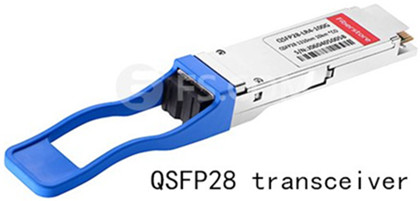
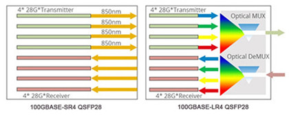
There are mainly two 100G QSFP28 transceiver versions: 100GBASE-SR4 QSFP28 transceiver and 100GBASE-LR4 QSFP28 transceiver. The former is specified to operate over multi-mode fiber (MMF) with the maximum link length of 70m on OM3 and 100m on OM4, while QSFP28 100GBASE-LR4 is standardized to work through single-mode fiber (SMF), able to realize 10km link length. The image below shows the working principles of 100GBASE-SR4 QSFP28 (left) and 100GBASE-LR4 QSFP28(right).
Why Choose QSFP28 Transceiver?
Since its surge, the QSFP28 transceiver has gained increasing popularity among enterprises or organizations, as it increases density and decreases power and price per bit. 100G QSFP28 makes it as easy to deploy 100G networks as 10G networks. Listed below are specific reasons why choose QSFP28 for 100G transmission?
At the first point, QSFP28 increases front-panel density by 250% over QSFP+. Although QSFP28 has the same form factor and the maximum number of ports as QSFP+ module, the lane speeds are increased from 10Gbps to 25Gbps.
Next, QSFP28 breaks some limitations found in other 100G optics. For instance, in the first generation of 100G switches and routers, the smaller CXP form factor was used for cabling and the CFP or CFP2 was used for transceivers. This forced the equipment designer to make huge sacrifices. Besides, a switch with CXP port could not be used in any data center with SMF, and a router with CFP2 or CPAK ports was limited in bandwidth by the 8-10 ports that could fit on the front panel. Well, as for QSFP28, it’s designed to support both cables and transceivers. Within QSFP28, a 1 rack-unit (RU) switch can accommodate up to 36 QSFP ports on the front face plate. Many varieties of either transceivers or cables can plug into these ports. The cables can be either direct attach cables (DACs), commonly referred to as direct attach copper cables, or active optical cables (AOCs).
Finally, QSFP28 transceivers can use either VCSELs (for shorter distances on MMF) or silicon photonics (for longer distances on SMF). The advent of silicon photonics enables QSFP28 transceivers to support any data center reach up to 2km or more. Silicon photonics provides a high degree of integration; the CMOS chips are small enough to fit within a QSFP package. Silicon photonics is low-power; even WDM designs can fit within the 3.5W maximum of QSFP.
Conclusion
With the fiber optic technology becoming maturer and more available, the choice of high-bandwidth switches, routers, and adapters which feature QSFP28 will be diversified, ensuring data centers to scale to 100G networks with the simplicity as 10G networks. Fiberstore supplies a large number of QSFP28 transceivers available in QSFP28 100GBASE-SR4 and QSFP28 100GBASE-LR4 types. If you want to know more information about QSFP28 transceivers, you can visit Fiberstore.
Oznake: 100G, QSFP28, QSFP+ module, 100GBASE-SR4 QSFP28, 100GBASE-LR4 QSFP28, QSFP28-100G-LR4
komentiraj (0) * ispiši * #
Patch Cable Selection Guide to Fiber Optic Transceivers
petak , 13.05.2016.Nowadays, a huge number of bandwidth-hunger devices are housed in data centers, like clustered storage systems, backup devices, and various servers, which are all connected by networking equipment. These devices need reliable and scalable cabling structure for high performance and flexibility. For some large- or middle-sized enterprises, their billion-dollar business lie in the suitable deployment of fiber patch cords and fiber optic transceivers. Since there are many kinds of patch cables available in the market for transceiver modules to promote data transmission in enterprises’ data centers, it seems a little difficult to choose the right kind for such transceivers. This text tackles this issue and provides some selection guide.
When delve into this topic, it’s imperative to have a basic understanding of the fiber optic transceiver.
Fiber Optic Transceiver Basics
Fiber optic transceiver, just as its name replies, is a self-contained component that can both transmit and receive signals. In most cases, this transceiver is plugged in devices such as routers or network interface cards which offer one or more transceiver module slot. In its whole signal transmission process, the transmitter takes an electrical input and converts it to an optical output from a laser diode or LED. The light from the transmitter is coupled into the fiber with a connector and is transmitted through the fiber optic cable plant. The light from the end of the fiber is coupled to a receiver where a detector converts the light into an electrical signal which is then conditioned properly for use by the receiving equipment.
According to different protocols, a wide range of optical transceivers are designed to support different data rates, including Gigabit SFP transceiver, 10G SFP+ transceiver, 40G QSFP+, etc..Take MGBBX1 for example, this Cisco 1000BASE-BX-U SFP is designed to be applied in Gigabit Ethernet (GbE) applications.

Fiber Patch Cord Details
Fiber optic patch cord, also called fiber jumper or fiber optic patch cable, consists of fiber optic cable terminated with different connectors on the ends. It’s typical application includes computer work station to outlet and patch panels or optical cross connect distribution center. While selecting patch cord, it’s recommended to take on from the following aspects, fiber cable mode, cable structure, connector types and so on.
Single-mode/Multi-mode Patch Cord
It’s known that fiber patch cords can be classified into single-mode and multi-mode fiber patch cord based on cable mode used. Single-mode patch cords, usually in yellow color, are with 9/125 fiber glass and has only one pathway for signal transmission, while multi-mode ones, often in orange, are with OM1 62.5/125 or OM2 50/125 fiber glass, and allow multiple pathways and several wavelengths of light to be transmitted with the large core.
Simplex/Duplex Patch Cord
According to the cable structure, patch cord can be divided into simplex and duplex versions. Simplex, also known as single strand, patch cable has one fiber, while duplex cable has two fibers joined with a thin web. Both simplex and duplex patch cords are available in single-mode or multi-mode versions. Because simplex patch cord has only one fiber link, its typically deployed for applications that only require one-way data transfer. For those applications, like fiber switches and servers, it’s advised to select duplex fiber optic cable for simultaneous and bidirectional data transfer. Additionally, there is also ribbon fan-out cable assembly (ie. one end is ribbon fiber with multi fibers and one ribbon fiber connector such as MTP connector (12 fibers), the other end is multi simplex fiber cables with connectors such as ST, SC, LC, etc.).
Patch Cord With Different Connectors
By connector type standard, fiber patch cord can also be divided. For instance, LC fiber patch cable is named as it is with LC connector. Similarly, there are SC, ST, FC, MT-RJ, E2000, MU and MPO/MTP fiber patch cables. Additionally, there are PC, UPC, APC type fiber patch cords, which are differentiated from the polish of fiber connectors.
How to Select Right Patch Cord for Transceiver?
After respective introduction to fiber optic transceiver and fiber patch cord, let’s go to the core issue—to choose the suitable cable type for transceivers.
In this part, I will take Cisco transceiver modules for example. For example, I need the suitable cable type for these two Cisco GbE transceiver modules, GLC-EX-SMD and MGBLX1. Then how to choose the right type? According to “Cisco Gigabit Ethernet Transceiver Modules Compatibility Matrix”, GLC-EX-SMD is the 1000BASE-EX SFP module that works through single-mode fiber (SMF) with LC duplex, and MGBLX1 is the 1000BASE-LX SFP module also for SMF with LC duplex. In such a case, since both two modules operate on SMF with LC connector, what I need is the with LC-LC duplex single-mode patch cable.
Conclusion
The above-mentioned example just lists one patch cable type for fiber optic transceivers. There are several commonly-aused patch cable types: LC-LC Simplex 9/125 Single-mode Fiber Patch Cable, LC-SC Duplex 9/125 Single-mode Fiber Patch Cable, LC-LC Duplex OM1 62.5/125 Multi-mode Fiber Patch Cable, ect.. Fiberstore supplies various kinds of high-quality patch cords for transceiver modules. You can visit Fiberstore for more information about patch cords.
Oznake: fiber patch cords, fiber optic transceiver, SFP, MGBBX1, MGBLX1
komentiraj (0) * ispiši * #
Fiber Optic Cable Basics: Construction & Certification Measurements
srijeda , 11.05.2016.Being one of the most popular and cost-effective means for communications, fiber optic cables have been installed in the backbone for years, as fiber makes communications at the speed of light possible. And their greater bandwidth and lower attenuation allow for longer distances and more channels compared with copper wires. The number of articles and papers on fiber optic cables is so large. Some are about their classifications (tight buffer/distribution/breakout/loose tube), some are on their advantage discussion (speed, distance, security), and others are meant to touch upon their related connector color codes (orange, yellow, blue). While in this article, still some basic information is included, like the construction and certification measurements.
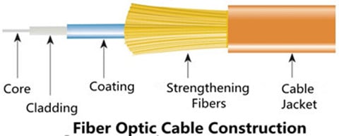
Fiber Optic Cable Construction
Fiber optic cable construction includes a core, cladding, coating, strengthening fibers, and a cable jacket.
Fiber Core
Fiber core refers to the light-carrying element at the center of the cable, transmitting optical data signals from an attached light source to a receiving device. The core is a single continuous strand of extruded silica glass or plastic that’s measured in microns (µm) by the size of its outer diameter. The larger the core, the more light the cable can carry. The two most common multi-mode sizes are 50 and 62.5 microns. Single-mode cores are 8.5–9 microns.
The cores of OM1 and OM2 multi-mode fiber (MMF) are made differently than the cores of laser-optimized OM3 and OM4 cable. OM1 and OM2 have a small defect in the core called an index depression. This enables them to be used with LED light sources. In contrast, OM3 and OM4 are manufactured without the center defect, which enables them to be used directly with VCSELS for greater speeds and distance. These OM3 and OM4 MMFs are widely used in Gigabit applications, especially in 10GbE transmission when they are used as the medium for 10GbE transceiver modules (ie. SFP-10G-SR).
Cladding
The optic cladding surrounds the fiber core. It functions as a boundary that contains the light waves and causes the internal refraction, enabling light to travel through the length of the fiber segment.
Coating
There is a protective acrylate coating that surrounds the core and cladding to protect them. This coating keeps the glass from dust and scratches that can affect fiber strength.
Strengthening Fibers
These components are to protect the core against crushing forces and excessive tension during cable handling, especially the installation and termination process. The materials can range from aramid yarn to wire strands to gel-filled sleeves.
Cable jacket
Fiber optic cable jacket is available in PVC and plenum-rated versions. The former type is typically used for patch connections in the data center, wiring closet, and at the desktop, while the latter kind is deployed when you need to route a cable through the buildings air plenum. Plenum cable has a flame-resistant jacket to inhibit the spread of fire.
Performance Measurements
Unlike copper cable, it’s easier to certify fiber optic cable, since it’s immune to electrical interference. When certify it, the following measurements are necessary.
Attenuation/Decibel Loss
Attenuation means the decrease of signal strength as it travels through the fiber optic cable, measured in decibels/kilometer (dB/km). Generally speaking, attenuation problems are more common to MMF.
Return Loss
This loss refers to the amount of light that is reflected from the far end of the cable back to the source. The lower the number, the better. For example, a reading of -60 decibels is better than -20 decibels. Like attenuation, return loss is usually greater with MMF.
Graded Refractive Index
This concept measures how the light is sent down the fiber, commonly mensurated at wavelengths of 850 and 1300nanometers. Compared to other operating frequencies, these two ranges yield the lowest intrinsic power loss (This is valid for MMF only.)
Propagation Delay
This is the time a signal takes to travel from one point to another over a transmission channel.
Optical Time-domain Reflectometry (OTDR)
This enables you to isolate cable faults by transmitting high-frequency pulses onto a cable and examining their reflections along the cable. With OTDR, you can also determine the length of a fiber optic cable because the OTDR value includes the distance the optic signal travels.
Notes on Fiber’s Speed & Modal Bandwidth
After introducing basic information about fiber optic cable, here, I’d like to mention two commonly-seen concepts: the first one, fiber’s speed which is not meaning the speed of the signal in the fiber, but the bandwidth potential of the fiber.
The second one, modal bandwidth which is caused by the fact that light in MMF travels in rays or "modes" that take different times to get to through the fiber, thus dispersion occurs. The longer the fiber, the greater the effect. This is the incentive driving fiber manufacturers to develop better MMFs.
Conclusion
Fiber optic cables are suitable for backbone, horizontal, and desktop applications, providing extremely reliable data transmission. They are less susceptible to temperature fluctuations, and can even be submerged in water or under sea. Fiberstore fiber optic cables come in various types with detailed specifications displayed for your convenient choice. These quality cables are designed with best-in-class performance. Besides, you can also find Push-Pull MPO cable, a kind of fiber patch cable with push-pull MPO connector here. For more information about fiber optic cables or patch cords, you can visit Fiberstore.
Oznake: fiber optic cables, MMF, 10GbE transmission, SFP-10G-SR, patch cords, Push-Pull MPO cable
komentiraj (0) * ispiši * #
MPO/MTP Cabling & Its Testing Issues
četvrtak , 05.05.2016.Data centers have never ceased their appetite for bandwidth. Virtualization, storage area networks, cloud computing, coupled with a host of other factors, all these boost that appetite. To meet such appetite means the use of a steady proliferation of fiber connections and ever-faster links. With the development of multi-fiber technology, MPO/MTP technology with multi-fiber connectors have been designed to support high-performance data center service.
The term MPO refers to multi-fiber push-on or also multi-path push-on, and MTP is a registered trademark of US Conec used to describe their connector. The US Conec MTP product is fully compliant with the MPO standards. As such, the MTP connector is a MPO connector. For simplicity, the following paragraphs will mention MTP only instead of MPO/MTP. MTP cabling solutions provide ideal conditions needed to realize high network performance, and accommodate bandwidth requirements both at present and in near future. This text aims to give basic information about MTP cable and its testing issues in details.
The Development of MTP Cabling
Prefabricated cabling systems and parallel array transmission systems, especially those 40G/100GbE networks on multi-mode fiber (MMF) generally use a MMF array connector called a MTP. This MTP connector is about the size of a fingernail, and uses a large rectangular molded plastic ferrule often with one or more rows of 12 fibers. MTP cables come in two variations (in addition to the pins/holes and keying options), cables with MTPs on either end, or breakout cables with an MTP on one end and single fiber connectors on the other end (just as image shown below).
The are two main drivers behind development of MTP cables. The first one goes to the ever-increasing need for cabling density in data centers. Cabling blocks airflow, so the denser the cable, the better the thermal management. And, as data center bandwidth steadily skyrockets to 10Gbps, 40Gbps, and 100Gbps, to even more, a dense multi-fiber cable becomes the suitable option. That is MTP cable.
The second one lies in the difficult and highly technical nature of field termination for fiber. Actually, it’s not generally considered to be suitable for field-installation. Rather, it’s usually factory terminated assemblies. Such modular factory-terminated MTP cable promises simplicity, lower cost, and true plug-and-play fiber connectivity.
MTP Cabling Testing Issues
It’s known that pre-terminated MTP fibers often experience the following processes: transportation, storage, and later bending or pulling during installation in the data center. All kinds of performance uncertainties are introduced before fiber cables are deployed. Thus, proper testing of pre-terminated cables after installation is the only way to guarantee performance in practical applications. In short, investing in factory-terminated fiber trunks to save time and decrease labor costs doesn’t really offer an advantage if the testing becomes a bottleneck.
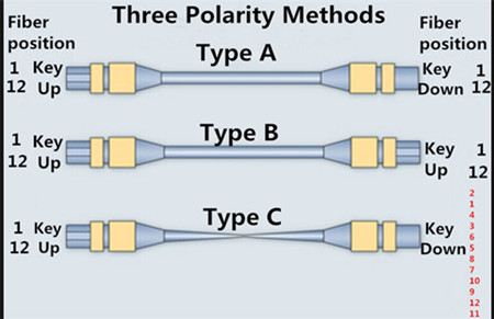
Testing and determining the fiber polarity are challenges meeting MTP cables. The simple purpose of any polarity scheme is to provide a continuous connection from the link transmitter to the link receiver. For array connectors, TIA-568-C.0 defines three methods to accomplish this: Methods A, B, and C. Deployment mistakes are common because these methods require a combination of patch cords with different polarity types.
More Bandwidth Means More Testing
The use of MTP cables for trunking 10-Gbps connections in the data center has steadily risen over the years. That 10-Gbps cabling assembly requires a cassette at the end of the MTP cable to accommodate legacy equipment connections. Now that 40-Gbps and 100-Gbps connections are available on the market, a migration path has emerged: remove the 10-Gbps cassette from the MTP cable and replace it with a bulkhead for a 40-Gbps connection. Then it might be possible to remove that bulkhead and establish a direct MTP connection for 100Gbps at a later date. The problem is that while this migration strategy proves as an efficient way to leverage the existing cabling, in comparison to 10-Gbps connections, the 40-Gbps and 100-Gbps standards call for different optical technology (parallel optics) and tighter loss parameters.
Thus, each time you migrate, you need to verify the links to ensure the performance delivery that the organization requires. As such, it’s imperative to go on more testing while bandwidth increases.
MTP Cabling Testing Guidance
So, how to operate the proper MTP cabling testing? The answer is simple. Do as the following says. It’s highly recommended to test all 12 fibers of the MTP simultaneously and comprehensively (including loss, polarity, etc.). That sort of test capability changes the fiber landscape, enabling installers and technicians to efficiently validate and troubleshoot fiber flying through the process by tackling an entire 12-fiber cable MTP with the push of a button.
Conclusion
MTP cable ensures simple fiber connectivity and meets bandwidth demands, offering the easy way for 40/100GbE migration path from 10GbE. The growing use of MTP fiber cable shows that the single MPO connection is your right choice. Fiberstore supplies a sea of MPO/MTP cables available in trunk and harness versions. Besides MTP cables, other cabling products are also available for various applications, like 487655-B21, a HP compatible SFP+ copper cabling product for 10GbE transmission. For more information about MTP cables or other cabling products, you can visit Fiberstore.
Oznake: MPO connector, MTP connector, MTP cable, cabling products, 487655-B21
komentiraj (0) * ispiši * #
