Do You Know How Fast Your Fiber Optic Internet Can Be?
utorak , 06.12.2016.It is no secret that the technology is continually evolving, so does the demand for consistent and accessible information and entertainment. From the old 56 kbqs crawl of dial-up, to the early 1 Mbqs copper connections and all the way to the existing popular 1 Gbqs, 10 Gbqs/40 Gbqs fiber optic connections, we’ve gone through a drastic improvement to maintain a stronger signal, a better connection, a faster speed. It seems that the intricacies of internet can get complicated, so how do you draw the line with your internet consumption and speed demands? So in this blog post, we explain how fiber optic works, why cause the boom in fiber optic speed and how fast fiber optic internet can be.
How Does an Fiber Glass Function in the Internet?
We know that fiber optic cable works like a bridge between the consumer and internet supplier. But how does this process actually work? To put it simply, fiber cable works by sending data as pulses of light through a glass fiber. At one end of the fiber, a laser or LED transmits data as light. At the other end of the cable, the light will be interpreted into data by the light-sensitive receptors.
If the above explanation is not clear to you, then here comes the more vivid description. Fiber optic cables consists of a strand of fiber glass wrapped in a protective jacket called cladding. Owing to the total internal reflection, light can go from one end of the core to the other end without ever changing its wavelength. More detailed information, please see an article entitled “A Quick Lesson In Fiber Optics”.
Fiber Optic Cable Types: Single-mode and Multimode Fiber
Single-mode and multimode fibers are the two broad categories of fiber core that can affect how light can travel through the cable. In single-mode fiber optic system, there is only one pathway or mode that light can travel along. While in multimode fiber optic system, seen in the below image, there are multiple pathways just like a circus funhouse with beams of light traveling along a variety of pathways through the core.
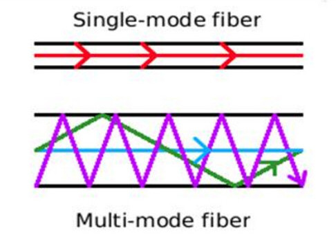
Theoretical, if you have one light beam traveling in both the single-mode and multimode fibers, the straight line beam of the single-mode fibers will reach its destination first. This difference is usually caused by the modal dispersion, which explain the reason why we often use the single-mode fibers for longer reach application.
WDM and Dark Fibers
The advent of WDM (wavelength division multiplexing) in the mod-2000s as a great breakthrough in fiber optics as it allows multiple channels to be carried at the same tine on a single fiber optic cable. There are all together CWDM and DWDM systems, CWDM or course WDM is the initial implement that allows 4 and 8 wavelengths, such as the Ethernet LX-4 standard which allowed a cable to carry four 3.125 Gbit/s data channels, resulting in 10Gbit/s aggregate.
In DWDM (Dense WDM) system, even though it is much more expensive, it can handle up to 160 data channels expanding basic a 10 Gbit/s system over a single fiber pair to over 1.6 Tbit/s.
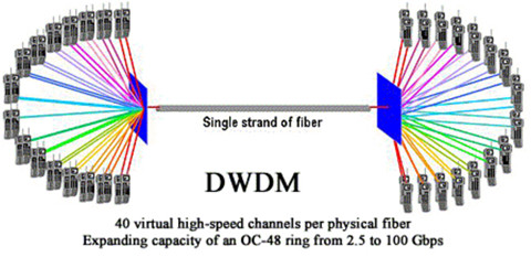
Figure 2 display different wavelengths can be bundled together in the same mode.
In terms of the new concept—dark fiber, it represents the unused cable laid in the network as space capacity, carrying high amounts of data at high speeds over hundreds of miles. Simply put, with DWDM, dark fiber network can easily increase bandwidth and allow more data to be send via optical fibers. And as the price reduces, dark fibers are gradually becoming more popular than ever.
How Do You Find out What Speed You Need?
This seems to be a noob question. As you can simply use the speed testing websites to discover the speed of your internet connection. And tracking the aspects of your internet use can give a better ideal of what speed you have and the speed that is optimal for you. What I want to express here is the common mistakes you will make.
It is not always the ISP’s fault, if your speeds are slower than what you expect. Several factors might have great impact on the accuracy of speeds. For example, the types of the hardware you have, the age/types of the line you have, and how busy the internet is at all time.
To find what speed you need depends on several different elements. How you plan to use the Internet, how many devices you have in your home, and how fast you expect to be connected are just a few factors that influence which speed is right for you. For office network, network speed under gigabit Ethernet is not sufficient.
Remember, speed is a maximum level, not a guaranteed one. As your desire for a faster connection increases, be sure you have the Internet speed that will exceed your technological needs!
The Next Steps for Fiber Optics
The modern commercial fiber optic system enjoys it stay in the Gigabit Ethernet speed. But we can look forward to the increases in the range of gigabits per second down speed, perhaps even breaking into the terabit range, in the not so distant future.
Oznake: fiber optic internet, fiber optic cable, DWDM
komentiraj (0) * ispiši * #
How Far Can You Bend Your Fiber?
srijeda , 23.11.2016.We know that stress and overstrain is a major enemy of the fiber’s lifespan, so cable installers must ensure that during the installation, fiber cables would not suffer from undesirable stretching or bending. Pulling, pushing and blowing are the three techniques used in wire management, which usually cause minor installation strains even for a seasoned installer. It is unavoidable, but fiber optic cables made of glasses have a limitation of bending ratio or tight diameter. If it do not exceed the certain diameter, the fiber will function well. Therefore it is essential for us to know how far cables can be bent. In fact, the maximum transmission distance of the fiber optic cable depends on the aspects like bend radius, tensile strength and usable duct space, which will be clearer illustrated in the following article.
Bend Radius
Bend radius is the curvature an optical fiber can bend without damage or shortening its lifespan via kinking. The smaller the rated bend radius, the more flexible the fiber. Just check the manufacturer’s spec for bend radius before purchasing the products. If no recommendations are available from the cable manufacturer, the cable should not be pulled into a bend radius smaller than twenty times the cable diameter. For example, a cable with an outer diameter of 5 mm, should not be bent smaller than 100mm radius during installation.
Maintaining proper bend radius is key in preventing service calls due to damage and signal loss in your optical fiber. Bend loss usually occurs when the fiber cable bends is tighter than the cable’s maximum bend tolerance, which might damage the fiber by causing micro cracks.
There are a couple of factors that may mitigate the problems of bend radius and the angles within them. If a fiber cable is being pulled or pushed through an empty duct or mini-duct, obviously there is less resistance to the cable and you can pull/push greater distances. If the coating of the outside of the cable and the inside of the duct are designed to reduce friction, you will be able to achieve greater distances as well.
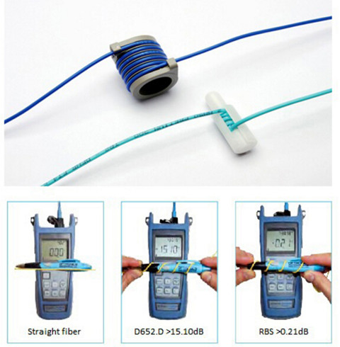
With well-designed bend insensitive fiber patch cables (seen in the above image), you can usually push a fiber cable as far as 90 degree angles in the run with minimized signal loss compared with the traditional fiber patch cables.
Tensile Strength
Just as the bend radius, fiber optic cables also have a maximum tensile strength. If the cable is being pulled through, it is better not to exceed the maximum tensile load. However, if the cable is being installed within a microduct or conduit, pushing the cable will apply no tensile force.
Over-stressing the fibers will not be noticeable until after installation since the cable outer sheath will elongate, whereas glass optical fiber will not. Ideally, a breakaway swivel should be used, however, where this is not possible, the installation crews should use a tension gauge attached to the pull-cord. As a rough approximation, 100 Newtons is equivalent to a 22lbf (pounds-force) load applied directly to the cable.
Usable Duct Space
The full space in the duct is not usable for cables because of horizontal and vertical bends and joints. Usable duct space should be at least 60%. 900µm and 250µm fibers are basically two kinds of fiber patch cables. 900µm fibers can easily be damaged with respect to the storage and wire management. 900 µm kinks easily, but is very flexible and installs easily. Sometimes, you have to balance ease of installation with toughness. The difference between 250um Loose-tube and 900um Tight Buffered Fiber have illustrated in the above article.
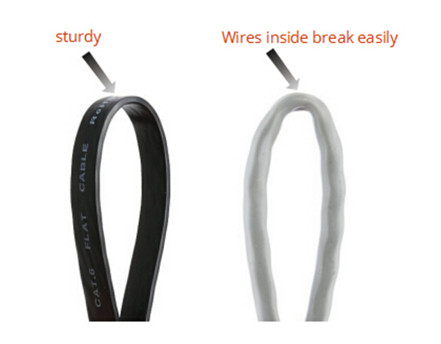
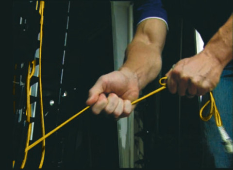
During the cable installation, you must get the fiber through walls—possibly in basements, attics, or crawl spaces, and then through floors, walls and, eventually, through a room to the CPE location. For rugged spaces where your fiber may suffer damage, such as basements or in conduits sharing space with electrical or other wiring, you may need a 3mm rugged sheathed cable that is flexible and crush resistant. The image below shows fiber optic cables being kinked. The flat cat5e cables (left) and common Ethernet cable (right) have different effect after bending.
Therefore, a good rule of thumb to use in planning your fiber drop is below: Bends (angles) = Friction—maximum distance of the pushable fiber
In addition to the above bend radius, here are some other areas to focus on to achieve maximum distance without damaging the cable: signal power and performance requirements for each device or revenue generating unit, locations of required splices, list of cable lengths required. When using duct or cable in conduit, keep in mind that freezing water in the conduit can crush the cable—and it may be wise to use microduct.
Summary
One of the challenges of installing fiber is to choose a cable with a very small bend radius, and it is tough enough to handle many different installation conditions. Once you have selected the appropriate fiber, plan your route to minimize bends and friction. By planning ahead and thinking carefully, you can save money by reducing the costs of those services. FS.COM, as a professional telecom vendor, offers a full range of cable management components, like the patch panels, cable manager & wire duct, fiber enclosures and so on. Some special cables including the bend insensitive fiber patch cables, flat fiber optic cables are also offered. If you have any interest, please send your request to us.
Oznake: Bend radius, wire management, fiber optic cable
komentiraj (0) * ispiši * #
The Benefit and Challenge of Patch Panel
srijeda , 19.10.2016.Patch panel is undoubtedly an essential component in cabling systems as it provide a simple, neat and easy-to-manage solution. For example, if you want to wire a network system that includes multiple wall ports, patch panels will not only allow you to terminate cable elements, but the signal to be connected to the final destination. No matter how big or small your business infrastructure is, patch panel is indispensable. So what is a patch panel? What are the exact benefits of using fiber optic patch panel? This article will provide some detailed information about the benefits and challenges of them.
What Is A Patch Panel?
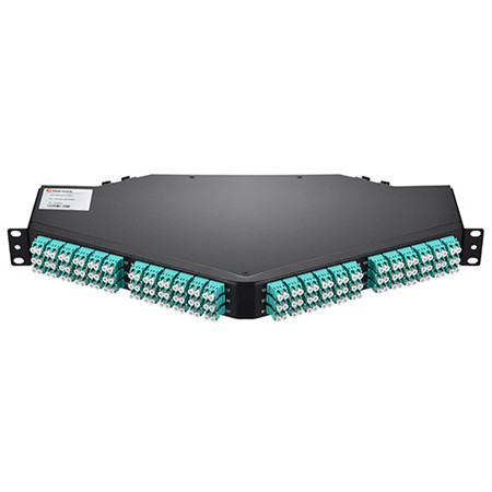
A patch panel is, in fact, an array of ports on one panel used to connect and manage incoming and outgoing LAN cables. The following image shows a 128 fibers MTP to LC/UPC OM4 1U 40GB QSFP+ Breakout Patch Panel. Each ports of patch panels connect fiber jumper cables to another port located elsewhere in your building. Circuits in an enterprise network can be easily rearranged by plugging and unplugging respective patch cords. Furthermore, patch panel provides a single location for all input jacks, which greatly simplifies the troubleshooting problems.
Patch panels are usually attached to network racks, either above or below network switches and take up 1U or 1.75 inches of space. Patch cords connect the ports in the patch panel to ports in the network switch, which creates permanent port connections to the switch that won't be interrupted during moves, adds and changes (MACs). Based on different standards, there are different types of patch panels. For instance, 48-port, 24-port and 12-port patch panels divided by the number of ports, or the more specific patch panels—Cat 5E, Cat 6, Cat 6A and Cat 7 cables. Since you have a basic understanding of patch panels, let’s move on the the next part.
The Benefit
A patch panel performs no other function except for acting as a connector, but it does offer a range of benefits:
- Use Standard Fiber Optic Cords
Since patch panel uses fiber optic cable to create interconnection, network designers can make changes and repairs without the delays and added expense associated with custom cabling.
- Flexibility and Scalability
The network can grow and change on-demand, without the costly, labor-intensive hassle of replacing channels end-to-end.
- Reduce Cable Congestion
Reduced cable slack means less clutter, less confusion and an easily organized, better-labeled cabling infrastructure. You can also manage cables in any direction–horizontal or vertical, front or back.
- Space Saving
By managing varying port densities and speeds in a single high-density patch panel, you save valuable rack space, helping to lower data center costs. A single patch panel can manage as many as (168) 10 Gb ports.
- Cost-Effectiveness
High-density and easy maintenance provide a low initial investment cost. With a patch panel, you can only buy the devices you need now, while leaving room for future expansion.
- Ease of maintenance
The advantage of using a patch panel is that it allows manual monitoring, testing, switching, routing, and other maintenance to be handled quickly because the cables in the front that connect to the more permanent cables in the back are configured and made so that changes can be made quickly and easily when needed.
The Challenge
With several patch panels available for sale, network users usually feel puzzled to select a patch panel solution with the features and capacity to meet their current needs, as well as the flexibility and scalability to adapt to and grow with the future needs. As noted before, patch panels can be divided into several types. According to different cable type, there are copper and fiber patch panels, which will be introduced in the next part.
Copper or Fiber Patch Panel?
A Patch panel can be connected with either fiber or copper cabling. The primary role of fiber patch panel is to direct signal at a required speed. It is the common sense that fiber is much faster than copper, and fiber patch panels are more expensive.
Structurally, copper panels have the 110-insulation displacement connector style on one side and 8-pin modular ports on the other. Wires coming into the panel are therefore terminated to the insulation displacement connector. On the opposite side, the 8-pin modular connector plugs into the port which corresponds to the terminated wires. With the copper panel, each pair of wires has an independent port. The following image shows the 48 Ports Shielded(STP) Cat6 Feed-Through 2U Gigabit Ethernet Patch Panel.

Fiber panels require two ports for a pair of wires. One port serves the transmitting end while the other handles the receiving end. While fiber panels tend to be faster than copper, this does not downplay the role played by the latter. And if there are more than one type of the fiber optic connector used in the network, patch panels with hybrid adapters are necessary. These adapters can then be used to plug individual fibers into other devices. The adapters on a fiber optical patch panel can come in a variety of different shapes.
Conclusion
To sum up, the patch panels make it easy to organize the fibers in an business or home network. What’s more, working with the fibers within the tray of the fiber optical patch panel protects the fibers from anything in the environment that could damage them. You can choose all range of fiber optical patch panel from FS.COM with high quality and competitive price. If you have interest, feel free to contact us.
Oznake: Patch Panel, fiber jumper cable, fiber optic cable
komentiraj (0) * ispiši * #
Understanding Industrial Fiber Optic Cable
ponedjeljak , 19.09.2016.Fiber optic cabling usually utilizes ruggedized jackets to ensure optimal performance in the face of extreme temperatures; exposure to UV/sunlight, oil, and solvents; and crushing impact, which makes it the ideal solution in any industrial environment where high-speed, high-bandwidth data solutions are needed. It can be used for campus and in-building data backbones to anchor an operation’s Ethernet, and also for point-to-point digital signal transmission. Today’s article will make a brief introduction to the basics of industrial fiber optic cable.

The Advantages of Fiber Optic Cable
Compared to the conventional copper wires, fiber optic cables are smaller and lighter than copper cables, extremely durable and intrinsically safe, with no risk of spark hazards. In addition, the following part lists several detailed information about the benefits of fiber optics.
- Higher carrying capacity—as the fiber optic cables are thinner than copper cables, more fibers can be bundled into a given-diameter cable. This allows more data information will be be carried across the network without interruption.
- Less signal degradation—it is known that the loss of signal in optical fiber is less than in copper wire.
- Lightweight—An optical cable weighs less than a comparable copper wire cable. Fiber-optic cables take up less space in the ground.
- Flexible—Because fiber optics are so flexible and can transmit and receive light, they are used in many flexible digital applications.
Types of Fiber Optic Cables
Fiber optic cabling can be segmented based on design criteria and installation environment:
Loose tube cables lay thinly coated fiber strands into unitized thermoplastic tubes, giving the fiber strands flexibility to move within the tubes and the cable, which makes it possess the ability to stand up to outdoor temperatures and harsh environments. Although loose-tube gel-filled fiber optic cables are used for high-fiber-count, long-distance telco applications, they are an inferior design for the Local Area Network applications where reliability, attenuation stability over a wide temperature range and low installed cost are the priorities.

Tight buffered cables contain an individual buffer on each fiber stand, allowing for easy handling and quick termination. For common small fiber counts, this design delivers a smaller cable diameter than loose tube cables and is best suited for indoor environments. The most common designs for tight buffered cabling are distribution and breakout. For applications like moderate distance transmission for telecom local loop, LAN, SAN, and point-to-point links in cities, buildings, factories, office parks and on campuses. Tight-buffered cables offer the flexibility, direct connectability and design versatility necessary to satisfy the diverse requirements existing in high performance fiber optic applications.
Singlemode and multi-mode cables are another common types of fiber optic cables. Single-mode fiber strands are designed to interface with laser optic light sources for distances beyond 300 meters, while multi-mode strands or MM fiber patch cords are designed to interface with LED and vertical-cavity surface emitting laser (VCSEL) light sources for short-distance cabling runs.
Considerations When Installing Fiber Optic Cables
If you are considering using fiber optic cables in your installation, take a moment to review the installation guides. Firstly, for industrial installations, it is critical to consider and evaluate the environment. Additionally, as the fiber optic cables are more susceptible to damage during the stress of installation, therefore there are two specifications for bend radii—Bend Radii before installation and Bend Radii after installation. All hardware and support structures should follow the recommendations of TIA-569 and NECA/BICSI 568 Standards documents. Last but not the least, use cable management straps or cable ties to support cable bundles. Make sure these implements are fastened snugly, but not tightly around cable bundles.
Conclusion
There is without saying that the advent of fiber optic cable solutions has been one of the best things to happen to technology in recent years. With the demand on technology ever-increasing, fiber optic cables are becoming the preferred method of transmission over traditional coaxial solutions. FS.COM offers a full range of optical devices, such as fiber optic cable, optical transceivers, DAC/AOC cables and so on. Fiber patch cables LC to LC and LC LC single mode patch cord are provided with high quality and low price. If you have any requirement, please send your request to us.
Oznake: fiber optic cable, Fiber patch cables LC to LC, LC LC single mode patch cord
komentiraj (0) * ispiši * #
The basics of Ethernet
petak , 09.09.2016.In today’s telecom field, Ethernet has been utilized at various levels of the control hierarchy. Since Its standardization in 1980, Ethernet has become the most widely installed local area network (LAN) technology either in the office or the enterprise network for high-end controller. We talk about Ethernet every day, however, people without decades of experience can hardly say they know everything about Ethernet. Therefore, this article are here to provide a foundation of Ethernet basics to improve your understanding of networking in general.
What Is Ethernet?
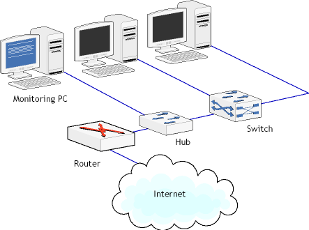
Ethernet is the most widely used LAN technology that serves as one of the main methods for connecting a computer or network to an Internet hub. The origin of Ethernet was the idea of connecting several computers together in a network via coaxial cables; since that time it has evolved into a much more sophisticated system that uses specialized Ethernet cables that connect to a central hub or router to network several computers together. Modern technologies made it possible for Ethernet networks to span tens of kilometers but this doesn’t change the local nature of Ethernet. The picture below shows a network connection with router, hub and switch.
For users who have little experience in telecommunication field, they usually consider Ethernet as a synonym for Internet. In fact, these two terms are similar, but they are different from each other. Internet is global in its nature, while Ethernet is a LAN network. An Ethernet network allows many computers or optical devices to connect to one another, this is done with the help of special Ethernet hardware and Ethernet protocols, which will be explained in the below part.
Ethernet Hardware
Ethernet hardware are indispensable for the operation of Ethernet network. There are three main elements of Ethernet hardware: Ethernet cards, Ethernet cables, and Ethernet hubs and routers.
The Ethernet cards or adapter is the component that is plugged into the computer and the Ethernet cable connects them to the rest of the network. Owing to the Ethernet adapter, a computer can send and receive data packets from the other segments of the network and/or the Internet.
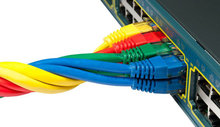
Ethernet cables is the medium that carries data in both packets to and from the computers, hubs, and routers in the Ethernet network. It usually comes in a number of styles, with the most common being Category 5, Category 5e or Category 6 cables. This type of cable are twisted copper cables that contain several wires which allow for the transfer of data in both directions to and from the computer. Cat 5e and Cat 6 cables are now the most commonly used Ethernet cable on the market. Network organizers are willing to turn to this copper cable rather than fiber jumper for its reliable performance and low cost. The following image shows the colorful category copper cables.
Ethernet hubs and Ethernet routers are the another important components of Ethernet network that mainly serves as a bridge to the internet. The router connects to the modem, which carries the Internet signal, sending and receiving data packet requests and routing them to the proper computers on the network. Even if a network isn't being used and only a single computer is present, in most cases that computer will connect to the modem by means of an Ethernet cable (or if a wireless router is being used, then the router will be connected to the modem). Hubs acts as a common connection point for devices in a network. It is used to connect segments of a LAN. When a packet arrives at one port, it is copied to the other ports so that all segments of the LAN can see all packets.
Ethernet Protocols
In addition to Ethernet hardware, another component that is required in order for Ethernet to work is a set of rules that define the communication within the Ethernet and with external networks. This set of rules is called Ethernet protocols, and there are tens of them used for communication within the Ethernet. As a network standard, each version of Ethernet includes specification for the physical network layer: how the signals will be sent and received. In order two devices on a network to be able to communicate successfully, it is mandatory that both devices use the same protocol. I cannot discuss all the protocols here, just take Carrier-Sense Multiple Access/Collision Detection (CSMA/CD) protocol as an example, which ensures that there are no collisions on the network and it is one of the most important Ethernet protocols.
Conclusion
What has been discussed in the above article is the basics of Ethernet knowledge including the definition, components and Ethernet protocols. Ethernet is such a big topic that it is not possible to be very detailed about it. But I still hope that this article about Ethernet basics is useful. FS.COM is a professional telecommunication manufacturer. Our optical devices are large in stock and can be shipped all around the world. Fiber optic cables like LC to SC patch cord, ST-LC patch cord, LC LC single mode fiber patch cable are provided at minimum prices. If you have any interest of today’s topic or any of our products, you can send your request to us.
Oznake: Ethernet, lan, Cat 5e, Cat 6, fiber optic cable, fiber jumper, LC to SC patch cord, ST-LC patch cord, LC LC single mode fiber patch cable
komentiraj (0) * ispiši * #
Considerations About Fiber Optic Cable Installation
petak , 15.07.2016.It’s true that fiber optic cable, based on optical technology to carry information between two points, have become increasingly important in fiber optic systems. This cable is often attached with the same or different connectors on the ends to connect devices, for example, LC LC multimode patch cord (LCs on both ends). When used in premises, fiber optic cables can be used as backbone cabling in a standard structured cabling network, connecting network hardware in the computer room. And when applied in optimized fiber optic networks, they go directly to the work area with only passive connections in the links. They can be installed indoors or outdoors using several different installation processes. One of my recent blogs has talked about safety issues about fiber optic cable installation. Today, this article still focuses on its installation, but from other aspects, including the general guidelines, its pulling tension, bend radius, and so on.
When deployed outside, fiber optic cables may be direct buried, pulled or blown into conduit or innerduct, or installed aerially between poles. When used outside, they can be e installed in raceways, cable trays, placed in hangers, pulled into conduit or innerduct or blown though special ducts with compressed gas. The installation process depends on the nature of the installation and the type of cables being used.

Installation General Guidelines
First point to mention is that fiber optic cable is often custom-designed for the installation and the manufacturer may have specific instructions on its installation. So, it’s highly recommended to follow the cable manufacturer’s suggestions. Often, it’s necessary to check the cable length to make sure the cable being pulled is long enough for the run, so as to prevent having to splice fiber and provide special protection for the splices. Of course, it’s better to try to complete the installation in one pull. Prior to any installation, one should assess the route carefully to determine the methods of installation and obstacles that are likely to be encountered.
Pulling Tension
Fiber optic cable is designed to be pulled with much greater force than copper wire if pulled correctly, but excess stress may harm the fibers, potentially causing eventual failure. Cable manufacturers install special strength members, usually aramid yarn, for pulling. Fiber optic cable should only be pulled by these strength members. Any other method may put stress on the fibers and harm them. During installation, swivel pulling eyes should be used to attach the pulling rope or tape to the cable to prevent cable twisting during the pull.
Besides, cables should not be pulled by the jacket unless it is specifically approved by the cable manufacturers and an approved cable grip is used. Tight buffer cable can be pulled by the jacket in premises applications if a large (~40 cm, 8 in.) spool is used as a pulling mandrel. It’s right to wrap the cable around the spool 5 times and hold gently when pulling.
It’s ill-advised to exceed the maximum pulling tension rating. It’s suggested to consult the cable manufacturer and suppliers of conduit, innerduct, and cable lubricants for guidelines on tension ratings and lubricant use.
On long runs (up to approximately 3 miles or 5 kilometers), one should use proper lubricants and make sure they are compatible with the cable jacket. If possible, an automated puller can be used with tension control and/or a breakaway pulling eye. On very long runs (farther than approximately 2.5 miles or 4 kilometers), one should pull from the middle out to both ends or use an automated fiber puller at intermediate point(s) for a continuous pull.
Bend Radius
When there are no specific recommendations from the cable manufacturer, the cable should not be pulled over a bend radius smaller than twenty (20) times the cable diameter. And after completion of the pull, the cable should not have any bend radius smaller than ten times the cable diameter.
Twisting cable
It’s known that twisting the cable can stress the fibers, thus in no case should one twist the cable. (Tension on the cable and pulling ropes can cause twisting.)
Use a swivel pulling eye to connect the pull rope to the cable to prevent pulling tension causing twisting forces on the cable.
Roll the cable off the spool instead of spinning it off the spool end to prevent putting a twist in the cable for every turn on the spool.
When laying cable out for a long pull, use a “figure 8” on the ground to prevent twisting. The figure 8 puts a half twist in on one side of the 8 and takes it out on the other, preventing twists.
Conclusion
Fiber optic cables have been widely deployed for computer net- works (LANs), closed circuit TV (video), voice links (telephone, intercom, audio), building management, security or fire alarm systems, or any other communications link. With its installation in large scale, it’s of great importance to know some basic points on cable installation discussed in this text. As for the fiber optic cables chosen for project, you can try Fiberstore, whose cables are available in many types, like SC fiber optic cable, LC SC cable, MTP cable. All are test- and quality-assured, suitable for both indoor and outdoor installation.
Oznake: fiber optic cable, connectors, LCs, LC LC multimode patch cord, SC fiber optic cable, cable installation
komentiraj (0) * ispiši * #
Fiber Optic Termination Overview
srijeda , 13.07.2016.It’s known that fiber optic termination methods vary based on the types of fiber optic cable being terminated, the style of connectors or splices used and the termination process appropriate for that connector. Generally speaking, fiber optic cable can be terminated in two ways—connectors that mate two fibers to create a temporary joint and/or connect the fiber to network equipment, and splices which create a permanent joint between the two fibers. Each termination method must have two primary characteristics: good optical performance (low loss and minimal reflectance) and high mechanical strength. As such, the terminations can be made in the right style, installed in a manner that provides low light loss and back reflection and protected against the expected environment, dirt or damage while in use. This passage mainly talks about the first method: connector.
Most fiber optic connectors are plugs or so-called male connectors with a protruding ferrule that holds the fibers and aligns two fibers for mating. Choosing a connector type for any installation should consider if the connector is compatible with the systems planned to utilize the fiber optic cable plant, if the termination process is familiar to the installer and if the connector is acceptable to the customer. If the systems are not yet specified, patch cords with different connectors on each end (e.g. LC ST patch cable) may be necessary.
Choice of Fiber Optic Connector
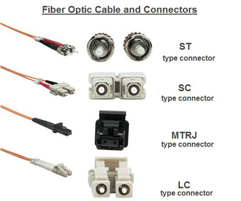
Fiber optic connectors are manufactured in different styles (say, ST, SC, LC, MT-RJ) that attach to the fibers in a fiber optic cable (LC to LC fiber cable single mode) by a number of methods, such as epoxy polish, prepolished/splice, etc.. ST is one of the most popular connectors for multimode networks, like most buildings and campuses. SC is a snap-in connector that is widely used in singlemode systems for it's excellent performance and multimode systems because it was the first connector chosen as the standard connector for TIA-568. LC uses a 1.25 mm ferrule, half the size of the ST. Otherwise, it's a standard ceramic ferrule connector, easily terminated with any adhesive. MT-RJ is a duplex connector with both fibers in a single polymer ferrule. It uses pins for alignment and has male and female versions, basically obsolete nowadays.
Termination Methods
Several termination methods are available for fiber optic cables, and the following passages list three terminations: adhesive termination, crimp/polish termination and prepolished termination.
Adhesive Termination
Epoxy Polish: The fiber is glued into the connector with two-part epoxy and the end polished with special polishing film. This method provides the most reliable connection and lowest losses. The epoxy can be allowed to set overnight or cured in a special oven. A “heat gun” should not be used to cure the epoxy as the uneven heat may not cure all the epoxy or may overheat it which will prevent curing.
Hot Melt: This connector is similar to the epoxy/polish connector but already has the adhesive (a heat set glue) inside the connector. The adhesive is liquefied in an oven before the fiber can be inserted. The fiber is secured when the adhesive cools.
Anaerobic Adhesives: These connectors use a quick-setting adhesive instead of the epoxy. They may use a single part adhesive or an adhesive and set- ting agent. Some adhesives do not have the wide temperature range of epoxies, so they should only be used indoors unless otherwise specified.
Crimp/Polish Termination
These connectors use a crimp on the fiber to hold it in the connector ferrule. The fiber can be polished like an adhesive connector or cleaved with a special tool. Insure the crimp is made properly to prevent fiber pistoning (pulling back or pushing forward in the connector ferrule.)
Prepolished Termination
These connectors have a short stub of fiber already epoxied into the ferrule and polished. Termination requires cleaving a fiber, inserting it into the back of the connector like a splice and crimping. The loss of these connectors will generally be higher than adhesive connectors, since they include the connector loss plus a splice loss in every connector.
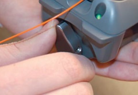
To ensure low loss, the fiber must be cleaved properly, which requires a good cleaver and good technique. Insure the crimp is made properly to prevent fiber pistoning. The termination process can be monitored with a visual fault locator.
Termination Process
Connectors can be installed directly on most cable types, including jacketed tight buffer types like simplex, zipcord and breakout cables, where the where the aramid fiber strength members in the cable are crimped or glued to the connector body to create a strong connector. Connectors can be attached to the 900 micron buffered fibers in distribution cables, but the termination is not as rugged as those made to jacketed cables, so they should be placed in patch panels or boxes for protection. The 250 micron buffered fibers in loose tube cables cannot be easily terminated unless they have a reinforcement called a breakout kit or furcation kit installed, where each fiber is covered by a larger plastic tube. Generally loose tube and ribbon cables are terminated by splicing on a terminated pigtail.
Cables can be pulled with connectors already on them if, and a big if, you can deal with two issues: First, the length must be precise. Too short and you have to pull another longer one (it’s not cost effective to splice), too long and you waste money and have to store the extra cable length. Secondly, the connectors must be protected. Some cable and connector manufacturers offer protective sleeves to cover the connectors, but you must still be much more careful in pulling cables. You might consider terminating one end and pulling the unterminated end to not risk the connectors.
When special tools are required, use them in the appropriate manner. And once installation is completed, connectors should be covered with an appropriate dust cap and stored in a safe location awaiting testing or connection to net- work equipment.
Conclusion
Fiber terminations must also be of the right style to be compatible to the equipment involved and be protected against the environment in which they are installed. When several connector types are all acceptable, or only one connector type is available but not ideal for the installation, the installer should discuss the merits of other types before committing to the project.
Oznake: fiber optic termination, fiber optic cable, connectors, LC ST patch cable, LC to LC fiber cable single mode
komentiraj (0) * ispiši * #
Learning Five Ways to Test Fiber Optic Cables
srijeda , 29.06.2016.In this technological world filled by fiber optic systems everywhere, one won’t fail to enjoy the benefits brought by fiber optics in daily life. In a whole fiber optic system, the most essential part should be the fiber optic cable. This cable is made up of incredibly thin strands of glass or plastic capped with the same (eg. ST ST fiber cable) or different connector types (LC ST patch cable) on the ends, used as the medium to carry information from one point to another with light-based technology. Just like electricity that can power many types of machines, beams of light can carry many types of information, so fiber optics do great to people in many ways, like broadcasting, transportation, medicine, etc..Along with the heavy use of fiber optic cables, testing the installed cables also gains importance in practical use. Since there are many standards available for testing, some people may get confused. But don’t worry. This text is written with an attempt to clear off this confusion.
Testing Principles
Generally speaking, five ways are listed in various international standards from the EIA/TIA and ISO/IEC to test installed cable plants. First three of them use test sources and power meters to make the measurement, while the last two use an optical time domain reflectometer (OTDR). Let’s first see the different results from these methods, and then delve into each one.

The use of source and power meter method, also known as “insertion loss”, simulates the way the actual network uses the cable plant. The test source mimics the transmitter, and the power meter the receiver. But insertion loss testing requires reference cables attached to the source and meter to connect to the cable under test. This insertion loss test can use 1, 2 or 3 reference cables to set the “zero dB loss” reference for testing. Each way of setting the reference gives a different loss. While OTDR is an indirect method, using backscattered light to imply the loss in the cable plant, which can have large deviations from insertion loss tests. OTDRs are more often used to verify splice loss or find damage to cables.
Source/Power Meter Method
In source and power meter method, all the three tests share the same setup (shown below), but the reference power can be set with one, two or three cables as explained next. In general, the 1 reference cable loss method is preferred, but it requires that the test equipment uses the same fiber optic connector types as the cables under test. If the cable (ST ST fiber cable) has different connectors from the test equipment (SC-SC on the tester), it may be necessary to use a 2 or 3 cable reference, which will give a lower loss since connector loss is included in the reference and will be subtracted from the total loss measurement.

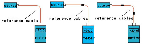
Reference per TIA OFSTP-14 (1 Cable Reference)
This method, formerly called method B, uses only one reference cable. The meter, which has a large area detector that measures all the light coming out of the fiber, effectively has no loss, and therefore measures the total light coming out of the launch reference cable. When the cable is tested as below, the measured loss will include the loss of the reference cable connection to the cable plant under test, the loss of the fiber and all the connections and splices in the cable plant and the loss of the connection to the reference cable attached to the meter.
Reference per TIA OFSTP-14 (2 Cable Reference)
This one, formerly called method A, uses two reference cables with one launch cable attached to the source, and the other receive one attached to the meter. (The two cables are mated to set the reference.) Setting the reference this way includes one connection loss (the mating of the two reference cables) in the reference value. When one separates the reference cables and attaches them to the cable under test, the dB loss measured will be less by the connection loss included in the reference setting step. This method gives a loss that's less than the 1 cable reference.
Reference per TIA OFSTP-14 (3 Cable Reference)
Reference cables are often patch cords with plugs, while the cable under test has jacks on either end. The only way to get a valid reference is to use a short and good cable as a "stand-in" for the cable to be tested to set the reference. To test a cable, replace the reference cable with the cable to test and make a relative measurement. Obviously this method includes two connection losses in setting the reference, so the measured loss will be less by the two connection losses and have greater uncertainty. Finally, here goes the picture showing the testing case with one, two, three reference cables.
OTDR Testing
With only one lunch cable, the OTDR can measure the length of the cable under test and the loss of the connection to the cable under test plus the loss of the fiber in the cable under test, and any other connections or splices in the cable under test. However, this method doesn’t test the connector on the far end of the cable under test, because it isn’t connected to another connector, and connection to a reference connector is necessary to make a connection loss measurement.

If a receive cable is used on the far end of the cable under test, the OTDR can measure the loss of both connectors on the cable under test as well as the fiber in the cable, and any other connections or splices in the cable under test. The placement of the B marker after the connection to the receive cable means some of the fiber in the receive cable will be included in the loss measured.
Conclusion
Hope this article is helpful for you to understand various methods existing to test fiber optic cables. For more information about testing methods or testing tools, you can directly connect me at Linkedin@Fern Xu (Fiberstore).
Oznake: fiber optic cable, LC ST patch cable, ST ST fiber cable, cable testing methods, source and power meter, OTDR
komentiraj (0) * ispiši * #
Three Factors That May Destroy Fiber Optic Cables
srijeda , 06.04.2016.Fiber optic cable, which has become the essential component of nearly all modern computer and communications systems nowadays, has been deployed all over the world. Where there is a city, there are thousands of fiber optic cables connecting people to the networking systems. Without them, it’s hard get the information in real time. But there is a problem that once the fiber optic cable is damaged or cut, it may cause a big loss because of the network disruption. And we know that fiber optic cable is made up of pure glass, in some cases, it may be very fragile. This article gives you three factors that may destroy the cables.
Environment
The environment is the first thing you should take into consideration. Because in the extreme weather conditions, such as hurricanes, mud slides, flood and ice storms, ect., fiber optic cable would suffer great damage. If water enters, a splice enclosure can freeze, then this will crush the fiber strands and leave you with a costly network outage. Additionally, lightning is also a factor to destroy fiber cables. When lightning strikes the ground, it will search for the best conductor available, even if it’s underground. If that happens to be the armor or trace-wire of your fiber cable, then damage to the cable sheath and even the fiber itself is very likely.
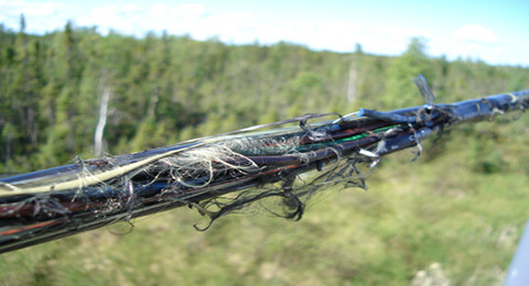
Human’s Destruction
Here human refers to the people who steal the fiber. They cut the fiber thinking it has value and can be sold in pieces. The most classical event is that a 75 year-old woman in Georgia (country in Asia) was digging with her spade, looking for copper, which she wanted to sell for scrap, when she accidentally cut the fiber optic cable that provided internet to 90% of Armenia. It is ridiculous. It is fiber but not copper! In addition, people vandalize the fiber cable in other ways, e.g. for gun practice. This especially happens in the rough parts of town which makes the cable repair work become dangerous. Furthermore, land disputes which cause artificial malicious damage of fiber are also a fiber damage reason.
Animals Chew & Bite
We can try to reason with humans and publicize our buried fiber cable, but there is nothing we can do about the cable damage causing by animals. Squirrel, a furry little nut eater, seems to be deeply fond of fiber cable sheathing besides nuts. We even doubt that the cable manufacturers of using peanut oil in the sheathing. Since they have a life-long drive to gnaw, squirrel is often responsible for extensive damage to fiber optic cable. Even metal armored cable can get cut in two by this furry critter. In addition, undersea cables aren’t exempt from cuts. Because there is another kind of animal under ocean that is likely to bite cables. It is shark. Why shark would like to eat fiber cables? Effect by magnetic fields is one of the explanation at present. We have no idea how we can combat these wayward rodents. Now, only thing we can do is always looking for ways to improve.
Notes on the Use of Fiber Optic Cables
After mentioning three common factors that may do harm to fiber cables, there goes the basic information about the use of fiber cables and their related fiber optic transceivers.
Fiber cables are used as the transmission medium of fiber optic transceivers for high data-rate transmission in gigabit applications, with distance reaching from only several hundred meters on multi-mode fibers (MMFs) to 10km, 20km, 40km, 80km on single-mode fibers (SMFs). Take Gigabit Ethernet (GbE) applications for example, when 1000BASE-LX SFPs (eg. MGBLX1) work through SMFs, 10km link length is made possible; and 1000BASE-SX SFPs (eg. MA-SFP-1GB-SX) operates via OM2 (MMF), the possible distance reach is 550m. So when you choose fiber optic cables for fiber systems, it’s necessary to figure out what the distance reach is required first, and then you can deploy the right fiber cable type for different applications.
Conclusion
So after you obtain a good understanding of the three factors that may destroy the fiber optic cables, you must master how to protect the cables. Now, waterproof fiber cables, armored fiber cables and the other outdoor cables which are designed to protect fibers in a harsh application environment are widely used in this field. You can buy these fiber optic cable as well as the related fiber optic transceivers (MGBLX1, MA-SFP-1GB-SX, etc.) in Fiberstore which are really reliable. Any questions, please let me know.
Oznake: fiber optic cable, SMFs, MGBLX1, MMFs, MA-SFP-1GB-SX
komentiraj (0) * ispiši * #
