Which Cabling Solution is Better for Your Data Center
srijeda , 31.08.2016.Although cabling only represents less than 10 percent of the overall data center network investment, it outlives most network elements and treated as the most difficult and potentially costly component. With the datacenter cabling ranging from 1G to 10G, 10G to 40G and even to 100G, more complex cabling is required to ensure a good service or scalability for troubleshooting. In practice, there is no exact solution that will meet all of the cable management needs. However, two kinds of cabling systems can be applied—unstructured system and structured system. Just follow the guidelines and illustration highlighted in the article will go a long way to ensure you with the information required for the successful deployment of a cabling infrastructure in your data center.
Unstructured Cabling System
Unlike the structured cabling system with a managed patch panel, a unstructured cabling only occurs when optical links are deployed point to point or device to device without installing patch panels. In this situation, cabling pathways become congested with an entangled mess of two-fiber optical patch cords. Likewise, routing new patch cords in ceiling or floor trays all the way across a data center each time a new device is deployed is extremely inefficient.
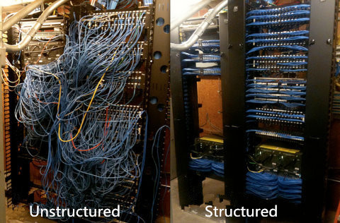
And this entanglement will bring difficulties in routing new patch cords in ceiling or floor trays all the way across the data center whenever a new device is deployed. That greatly influences work efficiency. What’s more, this system causes the overheating of data centers especially around the racks where cable clutter occurs.
Structured Cabling System
Structure cabling emerged as a way to better manage larger data center solution is a big step for the development of optical technology. Structured cabling system is a flexible, reliable and highly efficient for moving, adding and changing the infrastructure as the network grows. This kind of system requires additional investment on pre-terminated MPO cabling such as patch panel to create the cabling infrastructure.
Compared with the unstructured cabling, structured cabling architecture is generally easier to manage and more scalable. And, due to the use of trunked or shared horizontal cabling, it often carries a smaller cable footprint than direct-attach cabling. However, the flexibility of structured cabling presents potential downsides, including cost and link-loss budget. Nevertheless, existing large data centers will likely retain their structured cabling infrastructures, particularly for long-reach, zone-to-zone applications, where it generally remains the more practical choice. The following part will introduce 40G structured cabling solutions.
40G Structured Cabling Solutions
As noted before, structured cabling solutions allow for high consolidation of cabling into a compact patch panel, cabling and connectivity. The traditional duplex multimode SC or LC connections do not support 40G data rate standards, today the MPO technology is commonly found in cassette-based data center installation allowing for easy management and maintenance. Below are cabling solutions of 40G for cable management configurations with the use of MPO patch panel.
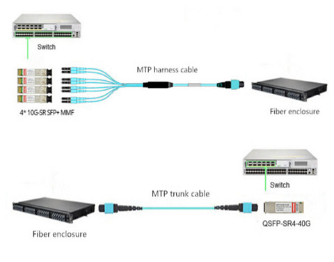
One method (seen in the above picture) uses MTP-LC harnesses to transition the MTP connector to LC leads through the use of fiber enclosure loaded with 4 fiber adapter panels (12xMTP Key-up/Key-down). This 12-fiber MTP to LC harness assembly breaks out 4 x LC uniboot legs connecting the SFP+ ports. The lengths of LC harness legs can be customized to adapt to different situations. But this often results in messy cable management. The other method uses MPO/MTP trunk cable and fiber enclosure loaded with 4 MTP high density cassettes (2 x MTP-12 to Duplex LC/UPC 10G OM4) to realize the interconnection. This 96-fiber 1RU rackmount fiber enclosure connects fiber patch cables LC to LC and MTP trunk cable. This method is specially used when the 4xLC ports are not located in close proximity on a single device or are being split between multiple devices. Because it’s more manageable to land the MTP trunk cables into fiber enclosure with individual LC ports for 4xLC patch cables.
Conclusion
Choose the most suitable cabling to support present and future network technology is essential for the long-standing performance of the data center. Structured cabling using an MTP cabling infrastructure is suitable for current 10 Gigabit Ethernet environments while maintaining protection for 40 Gbps environments and beyond. Compared with unstructured cabling, it might be a better solution for you. Except for the right knowledge of a structure cabling, the right tools, patience and discipline are also the key factors that will attribute to the masterpiece of your cable management in data center.
komentiraj (0) * ispiši * #
Brief Introduction to Network Adapter
petak , 26.08.2016.Generally for a home network, the most important consideration is the speed you have contracted for with your Internet service provider (ISP). And network adapters as an important element in wire management, are required to connect to the Internet with or without an Ethernet cable. There are many types of network adapters, an wireless one can help people connect to the home or office network as long as the computer is in the vicinity. This article will provide some information about network adapters that may be useful to potential buyers.
Main Features of Network Adapters
The wireless network adapter is quite similar to a memory stick in appearance. The device will usually insert into a USB port and has a LED light that indicates operability and power. The devices can be portable and quite effective. Some are slightly larger and may be the size of a credit card. Because of their size, the devices are convenient and easy to install. More designers are coming to appreciate the compactness of network adapters.
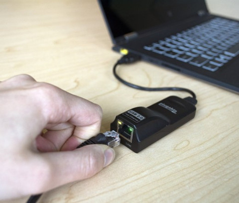
When the device is plugged in, it will scan for local networks to connect to and display them for the user. Users simply have to click the name of the network they wish to join. Any credentials that need to be provided should be provided, and this is all it requires to surf the network wirelessly. Most devices only require the credentials once, and it will boot each time it’s logged in.
The Important of Network Adapter
Network adapters are necessary for those who desire network connectivity. Network adapters bring so much more functionality and flexibility when it comes to connecting to the Internet. Wireless network adapters are even more desirable. Designers are recognizing that network adapters are instrumental to the success of the device. Local technology companies can provide network adapters at an affordable price to clients who need the functionality and the scalability. Network adapters are instrumental to connecting single or multiple devices to the Internet.
Software Drivers Are Necessary
Wireless network adapters need a piece of software called a device driver. These network drivers will allow applications to communicate with the network adapter hardware. When the network drivers are communicating with the hardware, the devices operate easier. Drivers can make current and past technology more compatible. If an upgrade is necessary from a PCI card or a PCMCIA, USB devices with update driver software is the preferable choice.
Backwards and Forwards Compatibility
Laptop computers will come equipped with a built-in WiFi card. When the wireless standards change and a new card is required, network adapters are usually backwards and forwards compatible. This is desirable if you want the newer and faster standard. For instance, most network adapters will support both the 802.11g standard and the 802.11n standard to ensure that they are both backwards and forwards compatible.
However to Ensure the Performance of Your Network Adapter
The network interface is where the data hits the computer. It’s the port or WiFi adapter that receives the data from the air or cable and translates it into something the computer can understand. No matter how fast the data arrives at the interface, it will only pass through as fast as the interface can process it. Many things can slow it down.
It’s important to remember that an interface that is capable of higher speeds than your network provides will not help things go faster. Spending money on a Gigabit network card won’t give you 1000 Mbps if your ISP is only supplying 25 Mbps.
Furthermore, a Ethernet cable in a cable management systems used to achieve the connectivity will also pose threat to the internet speed. Ethernet cables are presented in different categories. The most commonly used is Cat5, Cat5e and Cat6. CAT 5, rated at 100 Mbps; CAT 5e rated at 1000 Mbps; and CAT 6 rated at 10,000 Mpbs. CAT 5 is fine for most internet access through DSL or cable, while CAT 5e works well on connections over 100Mbps, as well as Gigabit business networks and home fiber optic connections. CAT 6 is probably overkill for most home networks, but is useful for business networks over 1 Gbps.
Other than cables used in home network, there are other factors that can throttle the performance of your network. Therefore, to use an external test server tests not only your home setup, including your adapter, but everything between you and the server doing the test.
Conclusion
To select the right adapter for your situation, you’ll want to have an adapter that exceeds the maximum speed of your network, while taking into consideration any likely future improvement. FS.COM offers a full range of fiber optic adapters including plug-in fiber adapter, bare fiber adapter, hybrid fiber adapter. All these products are terminated with LC, SC, ST, FC connectors. If you have any requirement of our products, please send your request to us.
komentiraj (0) * ispiši * #
Is It Worthwhile to Use Cat 7 Ethernet Cable?
utorak , 23.08.2016.Ethernet cables provide stable internet connection between electrical devices, which are standardized cables to facilitate easy communication between disparate electronic equipment. These electronic devices can either be fax machines, printers, scanners, or personal computers. Ethernet cables can be categorized into several types based on different specifications. Category 7 Ethernet cable, also refers to Cat 7, which is the wire used for cabling infrastructure of Gigabit Ethernet. it is known that Cat7 is the more expensive option compared to Cat 5e and Cat 6 cables. Users might be wondering whether it is worth the extra money to consider Cat 7 cables. The answer to this solution will be clearly introduced in this passage.
Quick Review of Cat 7 Cables
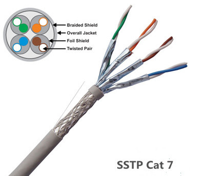
The Cat 7 cable refers to the transmission cord standard cable used in the 10G Ethernet and other Cat 5/Cat 6 downhill compatible networks. The Cat 7 cable is an 8-core safeguarded cable that each pair of cable has a shield. The program of Cat 7 cables is incompatible with RJ45. A Cat 7 cables can offer performance of up to 600MHz, which is 6 times as fast as cat 5e and 2. 4 times as fast as cat 6. Besides this, Cat 7 cable, whilst being the more expensive option, is also considered the most durable, and has a longer lifespan than Cat 5 and Cat 6, improving its overall return on investment, and is the best choice for wiring with the future in mind.
Comparing Cat 7 Ethernet Cable With Cat 5/Cat 6 Cables
The mostly used Ethernet cables are not a brand name or , they are separated into different standard categories like Cat 5, Cat 5e, Cat 6 and Cat 7. Each one of them is backward compatible, meaning that you can plug a newer cable into a device created for a slower cable, and you will not have any compatibility problems. For companies that are still using the older Ethernet cables, maybe it is time for them to upgrade to a newer version. Cat 7 as the newly released category, opposes the better performance than the former Category Ethernet cables. The following chart shows the distinctions in different Ethernet Categories.
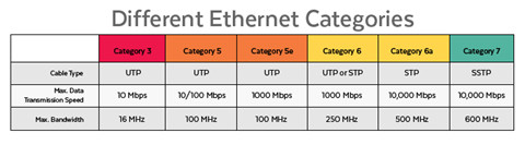
Cat 7 cables requires its twisted wires to be fully shielded known as Screen Shielded Twisted Pair (SSTP) or Screened Foiled Twisted Pair (SFTP) wiring, which completely eliminates alien crosstalk while significantly improving noise resistance. Thus it allows the user to get higher possible speeds even with longer cables. When compared at lengths of 100 meters of cable, the following numbers show the difference in Ethernet cable categories:
Cat 5 Ethernet cable is typically too slow for business networks, allowing the user to transmit up to 100 Mb/second speed at 100 Mhz. Cat 5e Ethernet cable allows up to 1 Gb/s internet speed with 100 Mhz. Cat 6 Ethernet cable allows up to 1 Gb/s, but cable lengths up to 55 meters can get internet speeds of 10 Gb/s at 250 Mhz. Cat 7 Ethernet cable is the newest cable category, operating at speeds of 10 Gb/s at 100 meters of cable and transmitting frequencies up to 600 Mhz.
Why Implementing Cat 7 Cable?
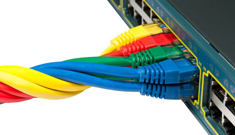
As noted before, Cat 7 cable is able to achieve higher transmission speed and longer distances than the preceding Ethernet cables like Cat 5, Cat 5e, and Cat 6 cables. What’s more, Cat 7 has an overall shield as well as individual shielding of every pair. Therefore it is much more resilient to interference compared to a CAT 5 cable. The following picture shows a SSTP Cat 7 cable.
To better meet the future demand, Cat 7 cables is an dispensable solution as it can create an expandable and flexible cabling system which will save you the expense of re-wiring for new features in the future! One point that we shouldn’t miss out is that Cat 7 cable has a copper cross-section than the Cat 5, which means the individual cores in Cat 7 are easier to work with. Then opt for Cat 7 cables will benefit you a lot.
Solid or Stranded Ethernet Cables
This refers to different methods the wires used within the cable. The solid cable uses one single piece of copper for an electrical conductor. The stranded cable uses multiple (and thinner) copper cables twisted together for the electrical conductor. This makes the stranded cable more flexible, perfect for navigating a complex space. The solid cable is far less flexible making it ideal for permanent installation in the walls or outdoor. This wiring method is not suitable for fiber optic cables like ST-LC patch cord.
Our Recommendations
In summary, careful planning and product selection will be the key to a successful installation. Resolution, distance, signal types, environment, and physical layout are the important factors that you should consider when choosing a transmission media. Cat 7 cable can support 10 Gigabit Ethernet with plenty of margin to spare, and it has pair-sharing capability, making it possible to use one cable to power several different devices at the same time utilizing each pair as needed. FS.COM offers the best and most versatile copper cables including Cat 5e, Cat 6 and Cat 7 products. Fiber optic cables are provided as well. Fiber patch cables LC to LC, LC LC single mode fiber patch cable, and SC to LC patch cable are all offered at minimum price. If you have any interest, please send your request to us.
Oznake: Cat7, Cat5, Cat6, Cat5e, Ethernet cables
komentiraj (0) * ispiši * #
Seven Tips for the Cable Installation
četvrtak , 18.08.2016.Cable installation can be a finicky thing. People without appropriate knowledge and training can not be capable of running cables, otherwise they will end up with network failure. End users might have the experience of running telephone cables, so that they want to take the risk of wiring network cables. In fact, telephone cables can tolerate quite a lot of errors, but that is not the case of the data cabling as it is quite sensitive to cable errors. Therefore, to avoid potential network error and reduce your risks of costly mistakes, here are several things you should know before the cable installation.
Using Cable Management
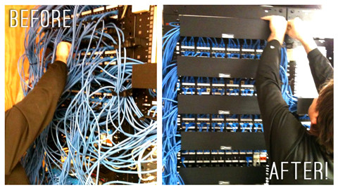
The first thing you should bear in your mind is that the cabling work won’t stop with the initial installation. More cables and optical devices will be added. Thus to make sure that you label appropriate cables, color-code cables, or implement some other kind of process to make it easier to identify cables later on. What’s more, adding ladder rack, rack-based cable management makes ongoing maintenance much, much easier. The following image can easily illustrate the importance of fiber cable management.
Running Cable in Parallel With Electrical Cables
Data cabling used UTP (unshielded twisted pairs) to achieve its goals. The magnetic field generated by the low voltage running through the cable is a critical component of the communications chain. When you run this unshielded cabling in parallel with electrical cables, that magnetic field is disrupted and the communication becomes noisy and garbled. In many cases, transmissions will simply not make it from Point A to Point B. In other cases, transmission rates will slow to a crawl as communications are constantly retried. If you have to go near electrical power lines, cross them in perpendicular instead. From a personal experience, a newly installed coaxial cable can be easily out of work if they are twisted around the overhead electrical cabling that ran between the two buildings.
Minding Distance Limitations of Your Cabling
It is known that the typical distance limitations for UTP cabling with up to 1 Gbps is 100 meters. However, if you're running cabling for some other purposes, such as 10 Gbps or 40 Gbps, be mindful of the distance limitations associated with the type of cabling you intend to use. For example, if you intend to run 10 Gbps for up to 100 meters over twisted pair cabling, you need to use Category 6A or better cabling. Or if you are running 10 Gbqs for up to 10 km, you need to use 10GBASE-LR SFP+with patch cord LC-LC.
Planning for Future Proofing
Maybe your network only provision 100 Mbps network connections to the desktop for now, even though the 1G Ethernet has become a ubiquitous standard. But suppose you are going to move to a new location and you need to install new cabling. Are you going to go with yesterday's best cabling technology or are you going to install something that will meet today's needs and your needs for the next few years?
Remember, the labor is the most expensive part of your project. While top-of-the-line cable won't be the least expensive option, you should consider reasonably high-end cable for your installation. Maybe you don't go with the absolute best, after all, many organizations won't need 10 Gbps to the desktop for quite some time but don't go for cheap, either.
Following the Cabling Standards
Many users might have the fallacy that there are only eight individual wires inside a cabling jacket, so why not terminate them at random as long as you use the same scheme at both ends? Of course, that is the bad ideas.
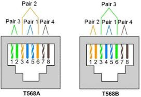
The cabling standard known as EAI/TIA-568-A and B are existed for a reason. This standard defines how the cables are twisted and placed in the jacket. If you deviate from those standards, you risk introducing noise and inefficiency into your cable plant that can have a negative impact on overall network performance. The following image shows UTP Cable Termination Standards EIA/TIA 568A and EIA/TIA 568B, and the only difference is that the green and orange pairs are terminated to different pins.
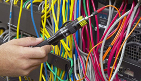
Testing the Cabling Results to Ensure Cabling System Properly Functioned
Once the cabling is installed, you should test every cable using appropriate tools to make sure that it will be suitable for its intended use. Fiber optic testing of newly installed systems not only verifies that the system meets its design requirements, but also creates a performance baseline for all future testing and troubleshooting of that system to support the evaluation of warranty claims. The following image shows a Visual fault locator (VFL), designed with a visible laser and universal adapter like FC, SC and ST etc., which can help user easily locate faults on the fiber link.
This testing typically includes verifying length and cable specifications matched to needs. If you need 1 Gbps transmission speeds, verify that the cable's properties will support that need. This testing result will ensure that the data necessary to properly evaluate any future system malfunctions will be available.
Ensure a Quality Installation With Quality Fiber Optics
The amount of information carried in two strands of optical fiber would require a copper cable four inches in diameter. When considering the space constraints, required bandwidth, and long distance transmission needs in today’s applications, fiber optic products are the only viable choice. Easy installation and upgrades allow you to meet future growth needs and install spare fiber today for a more economical choice than installing additional cables later. FS.COM gives you quality products for all your fiber optic needs to reduce your risk of network failure.
Conclusion
To sum up, improperly installed cabling can cripple network performance, create maintenance headaches, and lead to hidden costs. Besides the above tips, you are supposed to increase error-free work with trained technicians. Because the best practice in cable installation is a professional with the proper tools and certifications to ensure the proper installation of the network cabling. Note that a beginner who has little experience in cable installation should be instructed under a professional technician to proceed the cable installation.
Oznake: cable installation, cable management
komentiraj (0) * ispiši * #
Using A GLC-SX-MM Transceiver To Connect Gigabit Ethernet Network
utorak , 16.08.2016.If you are still using a 100BASE network, or GBIC transceiver for a small office, you may run into the limitations of last decade's technology. Because the 100BASE standard network is just fine for a small office, but it isn't sufficient to handle heavier network use. As your network expands, you might experience problems like: dropouts in your VoIP calls, Sluggish data retrieval speeds, or poor video streaming quality. If you have encountered any of this, maybe it’s time to start thinking about an upgrade to gigabit Ethernet, which moves at ten times the speed of traditional Ethernet. This article will explain the Gigabit Ethernet in the following aspects: the compatible SFP transceiver, the difference between twisted copper and fiber optic Ethernet.
Compatible SFP Transceiver
When contemplating an upgrade to gigabit Ethernet, there are a number of issues involved in the network transition. But one of the most immediate concerns people have is how much new hardware they'll have to purchase. The good news is that one of the basic issues providing connectivity is generally quite easy.
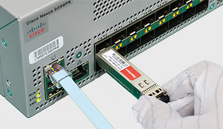
The representative of the optical transceivers for Gigabit Ethernet is Small Form-factor Pluggable (SFP). These Small Form-factor Pluggable slots allow transceivers like the GLC-SX-MM to be plugged in and provide instant gigabit Ethernet connectivity. In the last few years, when you purchased your networking equipment, it should have some industry-standard SFP ports, based on a Cisco standard. And you can only purchase the original expensive SFPs. However, the monopolized SFP market is unhealthy for the development of optical technology, nowadays people can appreciate the low price and high performance of compatible SFP transceivers from OEM vendors.
How to Ensure the Compatibility of the SFP Transceiver
Although the OEM or alternative party compatible SFP transceivers are much cheaper than the original ones, people are hesitated to use them. In fact, there are mainly two factors that will have an impact on the compatibility of the SFP transceivers. First, does the SFP optics require DDM function? Second, does the host equipment check the ID code and lock out alternative party components?
Certainly from our experience, most Cisco core equipment and routers do lock out all but Cisco ID SFP modules. We do not have an extensive report on what Cisco equipment does and does not lock out third party SFP.
The only way to know for sure is to try an authorized component if the host equipment rejects it. Remember, the compatibility has nothing to do with the functions of the transceiver, only in recognizing ID code and selecting to lock out third party SFP or not.
Fiber Optic Cabling Over Copper-wire Cabling
Choose to use copper-wire cabling or upgrade to fiber optic cabling in your offices is another consideration when installing a network. There is no doubt that fiber optics provide several advantages over copper, but it is more expensive than copper cabling. In addition, fiber optic supports far longer cable lengths than twisted copper.
Copper can only run for around 100 meters, whereas fiber can go between 200 and 500 feet, or more, without signal loss. Fiber has gives off no radio interference, allowing it to coexist more easily in an office with a lot of wireless devices. Because of the lack of interference, fiber is also harder to hack into than copper.
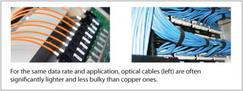
For equivalent data rates, optical cable is thinner and lighter than copper wire, and it does not need to be shielded. For these reasons, an optical cable is often lighter in weight and less bulky, and has a smaller bend radius, than the equivalent copper cable, especially with longer cables. These advantages of fiber provide more data center configuration flexibility.
Just as with copper, a standard GLC-SX-MM transceiver links fiber optic Ethernet with your existing equipment. Or the GLC-SX-MM-RGD transceiver is also just great for your network, which is the 1000BASE-SX SFP GLC-SX-MM transceiver with DOM support.
For future proofing, moving away from copper is probably a good idea. Fiber optics are growing steadily in popularity among businesses which have taken over large office buildings, created expansive complexes, or need to collaborate with remote offices in real time.
Additional Information
The biggest advantage of Cisco's SFP system is that it's entirely hot-swappable. It doesn't matter what the device is, from servers to your switch to simple Ethernet cards: If it has an SFP port on it, it can support a multitude of transceivers for different functions, through one standardized interface. In fact, that standardization means that third parties can produce transceivers which are as good as official Cisco units. So, if you decide that fiber optic gigabit Ethernet is what you need for your future business communications needs, the GLC-SX-MM transceiver is truly simple to install and use.
Conclusion
End-users are wondering about whether they should upgrade to higher-bandwidth network as the existing network like 100BASE standard is fine for their network. However, the transition to higher internet speed is going to happen sooner or later. There are several different gigabit Ethernet standards out there, so keep in mind to see which best fits your vision for the future of your business. Note that you'll need transceivers like the GLC-SX-MM to connect your existing devices to the new network.
Oznake: GLC-SX-MM, GLC-SX-MM-RGD, SFP optics
komentiraj (0) * ispiši * #
Stay For 40Gbps Network or Scale Up to 100G?
petak , 12.08.2016.The evolution of bandwidth for data transmission is unstoppable. From the 10Mbps, 100Mbps Ethernet to the 10G or 40/100G Ethernet, telecom manufacturers keep promoting higher internet speed to facilitate people’s daily life. Now, bandwidth speeds of 1Gbps to 10Gbps Ethernet capacity are commonly utilized around the world. However, with the increase in data center and cloud computing technologies, the demand for bandwidth speeds of 40G to 100G Ethernet is growing steadily for carriers and other data consumers.
Just like the dilemma of whether to use the fiber optic cable for high performance or adopt copper cable for the low cost, these high-end data consumers also have the doubt about 40G and 100G. Should we upgrade our capacity to 40Gbps or skip 40Gbpsand migrate directly to 100Gbps Ethernet? This article will help to draw an answer to this dilemma from the aspects of market trend for required bandwidth, cost and performance.
Upgrade Straight to 100G
According to today’s market trend, the tendency is to skip 40Gbps. With demanding users peeling off multiple 10Gbps channels, the 40Gbps pipe becomes quickly utilized. Carriers scaling up to 100Gbps, allows greater flexibility for one’s network infrastructure utilizing multiplexing solutions to carve multiple bandwidth channels from a single pipe. On another scale, the same is true for the consumer market where capacity is increasing from 1Gbps to 10Gbps, skipping 2.5Gbps levels, due to the flexibility and scalability 10Gbps provides at a very similar cost. In many cases, carriers and consumers have decided to skip 40Gbps and acquire 100Gbps for the following reasons and benefits:
![]()
- Cost Efficiency—From a network equipment standpoint, often it may be more cost-efficient to upgrade a 10Gbps link to 100Gbps, versus 40Gbps. Essentially, if you should require 60Gbps or say even 80Gbps, additional cards would be needed to support the link in the chassis, whereas a customer may utilize only one card to achieve more than twice the bandwidth at 100Gbps. 100Gbps allows the network to operate within a smaller footprint of a data center, which in turn, reduces power consumption dissipating less heat and thus lower operational costs.
- Lower Latency—100Gbps provides lower latency capabilities than 40Gbps; many carrier grade vendors are lowering latency on 100Gbps matching latency of traditional 10Gbps traffic.
- Flexibility—Creates options to provide multiple variations of delivery with handoffs ranging from 10Gbps, 40Gbps or the full 100Gbps pipes.
- Scalability—Although a customer may not utilize 100Gbps on day one, the ability is there to scale the network with no forklift upgrade at any point, future-proofing the solution well beyond capacity needs.
As consumer’s demands for higher bandwidth continues to rise, many equipment suppliers, who developed some of the first 100 Gigabit Ethernet Router Interfaces, are now working on developing 200Gbps, 400Gbps up to 1 Terabyte interfaces.
This article is not implying that there is no use for 40Gbqs bandwidth level technology. Instead, I suggest that many end consumers are looking to keep up with the acceleration of high bandwidth demands while maintaining the efficiency and technologies needed to support their network infrastructure requirements while reducing operating costs.
100G Optic Solutions
FS.COM 100G transceiver solution offers customers 100 Gigabit Ethernet connectivity options for data center networking, enterprise core aggregation, and service provider transport applications. Various of 100G transceivers including CXP, CFP, CFP2, CFP4 and QSFP28 are available for different applications. The following part will lists two cost-effective 100G solutions.
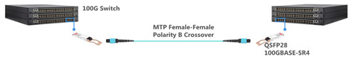
- QSFP28 to QSFP28 Interconnection
The QSFP28 is the exact same footprint as the 40G QSFP+, but is implemented with four 25Gbps lanes. To interconnect a multimode QSFP28 link, a 12-fiber MPO/MTP patch cable is required, while for single-mode link (100GBASE-LR4 QSFP28), a duplex LC single-mode patch cable is required. The interconnection of QSFP28 multimode link is similar with the case of QSFP28-100G-SR4 see in the following figure.
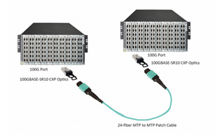
- CXP/CFP to CXP/CFP Interconnection
FS.COM’s 24-fiber MPO/MTP assemblies are ideal for 100GBASE-SR10 CXP/CFP to CXP/CFP interconnection in data center, since it is implemented 10 lanes of 10 Gbps. Among the 24 fibers, only 20 fibers in the middle of the connector are used to transmit and receive at 10 Gbps and the 2 top and bottom fibers on the left and right are unused. The following picture shows the interconnection between two 100GBASE-SR10 CXP ports.
FS.COM provides a full selection of 100G optics including CFP, CFP2, CFP4, QSFP28 (QSFP28-100G-SR4) and QSFP28 DAC cables just as listed above. All of our products are fully compatible with the original brand. In addition, our 100G transceivers offer significant advantages over existing solutions in terms of reduced power dissipation and increased density with the added benefit of pluggability for reduced first installed cost. If you have any requirement, you can send your request to us.
Oznake: 100GBASE-LR4 QSFP28
komentiraj (0) * ispiši * #
40G QSFP+: Data Center Bandwidth Provider
petak , 05.08.2016.With time passing by, the world’s data centers witness the rapid flowing of digital information whose volume grows at an ever increasing rate. The increase of server virtualization and cloud computing applications, coupled with the trend toward network convergence, all these are boosting today’s data center networks to become faster and more efficient than ever before. Date back to the past years, 100Mbps Ethernet is replaced by 1Gbps Ethernet which is then substituted by 10Gbps Ethernet. With 40GbE and 100GbE being available in the market, some companies or organizations can implement cut-through switching and flatter network architectures which can deliver more bandwidth, so as to reduce traffic latency and meet wireless computing needs.
To ensure the smooth 40GbE networking performance, one device is fundamental—40G QSFP+ (Quad Small Form-factor Pluggable Plus) transceiver. This QSFP+ transceiver interfaces a network device motherboard (for a switch, router, media converter or similar device) to a fiber optic cable, providing sufficient bandwidth to enable fully non-blocking switch fabrics.
40G QSFP+ Working Principlerinciple
40G QSFP+ transceiver is a hot-swappable module, integrating 4 independent 10Gbps data lanes in each direction for 40Gbps aggregated bandwidth. QSFP+ modules offer customers a wide variety of high-density 40Gbps connectivity options for data center, high-performance computing networks, enterprise core and distribution layers, and service provider transport applications. The release of the IEEE 802.3ba physical layer standard for 40G QSFP+ in 2010 specifies both fiber and copper cabling solutions, such as 40GBASE-SR4, 40GBASE-LR4 and 40GBASE-CR4.
40G QSFP+ Port typesrt types
Commonly used QSFP+ transceiver port types are 40GBASE-SR4 and 40GBASE-LR4.
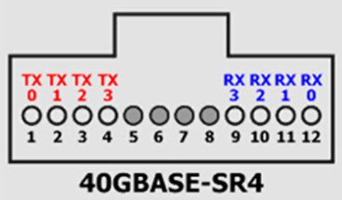
40GBASE-SR4
40GBASE-SR4 physical medium dependent (PMD) variant defines a 4 lane parallel optical interconnect for operation up to 100m link length over OM3 multi-mode fiber (MMF) and to 150m over OM4 MMF. It establishes high-bandwidth 40G optical links over 12-fiber parallel fiber terminated with MPO/MTP multi-fiber female connectors. Four of the twelve fiber for receive, other four for transmit, leaving the middle four fiber unused. Each of the four lanes operates at a data rate of 10.3125Gbps which is the same serial bit rate that was defined for 10Gb Ethernet links in the IEEE 802.3ae standard ratified in 2002.
40GBASE-SR4 PMD addresses the modern need for 40Gbps interconnects in the data center and takes advantage of lower cost 850nm Vertical Cavity Surface Emitting Laser (VCSEL) technology that is widely deployed throughout networking industries. As each of the 4 lanes in 40GBASE-SR4 operates at the same serial bit rate as a 10Gb Ethernet link, there is an opportunity for switching hardware vendors to utilize 40GBASE-SR4 as 4 separate 10Gb Ethernet interconnects. The problem is that 40GBASE-SR4 standard is not defined to be backward compatible with the existing 10GbE short reach interconnect standard.
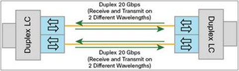
To address this issue, QSFP BiDi transceivers have been released into the market. A QSFP BiDi transceiver (e.g. Cisco QSFP-40G-SR-BD) transmits full-duplex 40-Gbps traffic over one dual-fiber LC-connector OM3 or OM4 MMF cable. It provides the capability to reuse 10-Gbps fiber infrastructure. In other words, it enables data center operators to upgrade to 40-Gbps connectivity without making any changes to the previous 10-Gbps fiber cable plant.
40GBASE-LR4
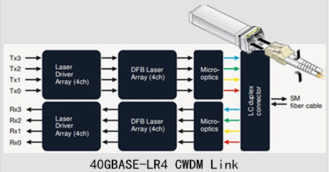
40GBASE-LR4 has two link options: coarse wavelength division multiplexing (CWDM) and parallel single-mode fiber (PSM). This passage mainly talks about the first one option.
40GBASE-LR4 CWDM QSFP+ uses a duplex LC connector as the optical interface, able to support transmission distance up to 10km over single-mode fiber (SMF). It converts 4 inputs channels of 10G electrical data to 4 CWDM optical signals by a driven 4-wavelength distributed feedback (DFB) laser array, and then multiplexes them into a single channel for 40G optical transmission, propagating out of the transmitter module from the SMF. Reversely, the receiver module accepts the 40G CWDM optical signals input, and demultiplexes it into 4 individual 10G channels with different wavelengths. The central wavelengths of the 4 CWDM channels are 1271, 1291, 1311 and 1331 nm as members of the CWDM wavelength grid defined in ITU-T G694.2. Each wavelength channel is collected by a discrete photo diode and output as electric data after being amplified by a transimpedance amplifier (TIA).
Cable Types for 40G QSFP+0G QSFP+
IEEE has specified standards for 40G transmission in both long distance and short distance, which are 40GBASE-SR4 and 40GBASE-LR4. As what has been mentioned above, the latter is suggested for 40G transmission over SMF in long distance up to 10km, while the former is for 40G transmission in short distance over MMF (often in with a 12-fiber MPO connector version)—OM3 (up to 100 meters) and OM4 (up to 150 meters). OM3 and OM4, which are usually aqua-colored, are accepted economic solutions for 40G in short distance with lower insertion loss and higher bandwidth. Besides, DACs are also chosen as the 40G cabling solutions sometimes, available in QSFP+ to QSFP+ DAC and QSFP to SFP+ cable versions.
Conclusionnclusion
40G QSFP+ transceivers support 40GBASE Ethernet, allowing flexibility of interface choice and great bandwidth for data centers. For your smooth 40GbE performance, Fiberstore supplies various cost-effective QSFP+ transceivers which are fully compatible with major brands, such as Cisco, Juniper, Brocade, and so on. Besides these 40G modules, SFP transceivers are also offered, like Cisco GLC-T, a Cisco compatible 1000BASE-T SFP. All these products are rigorously checked for quality and compatibility assurance. If you want such a module for your networking use, you can consider Fiberstore.
Oznake: 40GbE, 40G QSFP, 40GBASE-SR4, QSFP BiDi, Cisco QSFP-40G-SR-BD, sfp transceivers, Cisco GLC-T
komentiraj (0) * ispiši * #
In-depth Understanding of LC Duplex Connectors
utorak , 02.08.2016.As one of the small form factor (SFF) field polish connectors, LC duplex connectors are widely used for equipment cross-connects or interconnects in backbone, horizontal and work area applications for high-speed data transmissions. They provide a solution for high-density telecommunication rooms, LANs (Local Area Networks), public networks and fiber-to-the-desk applications. While talking about LC duplex, most just think them as the small useful tools which allow fast and easy field termination for fiber optic connectivity. Actually, LC duplex are more than what their design and appearance show. Their world are full of colors. This article guides the inner world of these LC duplex connectors from their several family members.
Standard LC DuplexC Duplex
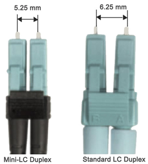
It’s known that the standard LC connector is developed by Lucent Technologies. Its connector body is squarish shape that is similar to SC connector, and has half the size of the SC. Standard LC duplex connectors are LC with a duplex configuration with a plastic clip. The fibers used to terminate in its 1.25mm ceramic ferrule can be both single-mode and multi-mode versions, such as LC to LC fiber patch cable single mode and LC LC multimode patch cord. Compared with SC, LC’s high-density design and 1.25mm ferrule double the port density, reducing space requirements on racks, enclosures, panels and faceplates. Nowadays, LC duplex connectors are still popular both in telcos and high bit rate LANs, etc..

Mini-LC Duplexplex
As a variation of standard LC duplex, the mini-LC duplex uses current industry-standard LC connectors, but allows closer ferrule spacing by using the duplex clip (usually with color coding)—mini-LC has a reduced center spacing of 5.25mm compared to a standard LC of 6.25 mm. This type of LC duplex connector is designed to operate with the Mini SFP modules and provide a higher density deployment for data center equipment.
LC Duplex with Uniboot Uniboot
LC duplex connector with uniboot is two LC connectors encased in a common housing with one boot, terminated on a single twin-fiber round cable. This type of connector is more compact compared to standard LC duplex. Fiber patch cables terminated with uniboot LC duplex connectors, are ideal for high-density cabling application since they reduce more fiber counts and greatly reduce cable management space. (The boots of an LC duplex connector can be configured with various versions according to different requirements. In addition to standard connector boots and uniboots, there are mini boots, BTW (Behind the Wall) boots, short boots, and 45 or 90 degree angel boots in the market.)

LC-HD DuplexD Duplex
In practical operation, it’s not easy to release the LC duplex connectors in patch panels, and sometimes thumbs and forefingers are not ideally suited to operate the release lever and pulling the connector. As such, LC-HD duplex connectors are designed to help deal with this issue. With a flexible “pull-tab” or “push-pull tab”, the LC-HD duplex connector can be disengaged easily from densely loaded panels without using the special tools which allows users easy accessibility in tight areas when deploying in data center high-density applications. Some types of LC-HD duplex connectors combine the advantages of uniboot, which make them more suitable to high-density cabling applications.

Keyed LC DuplexC Duplex
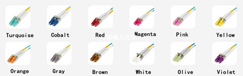
Keyed LC duplex connectors are available in 12 colors, thus creating a colorful LC world. Each color of the keyed LC duplex connectors represents a unique keying pattern which only allows its matched color-coded adapter mating. This kind of LC duplex connector can help segregate or identify of parts or paths within a network infrastructure, as well as reducing the risk of accidental or malicious network access, particularly in shared access areas or in secure hierarchical environments.
LC Duplex Connector Advantagesvantages
The LC duplex connector is designed in response to the growing needs for smaller and easier-to-use fiber optic connectivity. It simplifies moves, adds, and changes, and reduces installation time for field mountable connectors, time- and money-saving. Additionally, it doubles fiber density in shelves and outlets –lowering system costs again, as well as improves durability and reduces cross-connect rearrangement effort.
Conclusionnclusion
LC duplex connector uses an improved version of the familiar and user-friendly telephone plug, which provides a reassuring, audible click when engaged. The unique combination of small size and the click of connectivity makes the LC duplex the right choice for your network. With the increasing connectivity requirements. The family LC duplex connectors are sure to be enlarged. When you want to buy these connectors, Fiberstore is a good choice for many LC solutions. Besides LC solutions, SC solutions are also available for you,like SC patch cord, SC adapters, and so on. Visit Fiberstore for more information about LC and SC fiber optic solutions.
Oznake: LC duplex connectors, standard LC, LC to LC fiber patch cable single mode, keyed LC duplex, SC solutions, SC patch cord
komentiraj (0) * ispiši * #
