Introduction to Server Power Cord
petak , 09.06.2017.The power cord is an indispensable unit to support the work of power supply. Connecting the servers and PDU (power distribution unit), server power cord plays an important role in ensuring good electricity supply. However, the standard for the connector type and voltage level of power cord are different in different countries. To make the network system work with high performance level, it is necessary to choose a suitable power cord. This article will give an introduction to server power cord to help you make the choice.
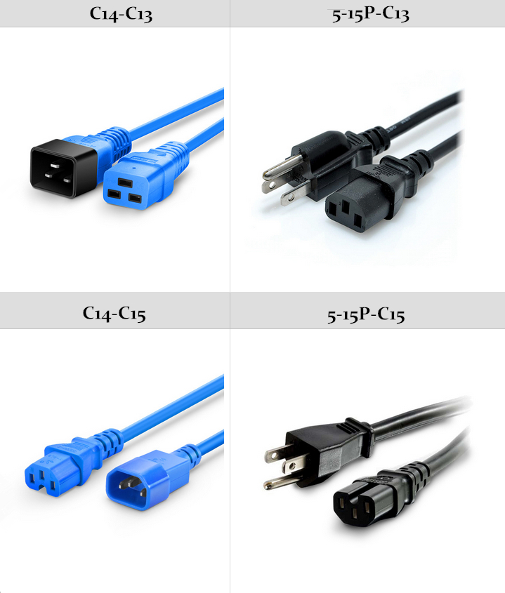
Although there are many different types of power cords used around the word, the structures of them are similar. In general, power cord consists of three parts: plug, cord and receptacle. The IEC60320 power cord and NEMA power cord are the most commonly seen types. The former one is commonly seen in US, while the latter one is widely used in North America and other countries that use the standards set by the NEMA. The following figure shows c13 to c14 power cord, nema 5 15p to c13 power cord, c14 to c15 power cord and nema 5 15p to c15 power cord, which are the most popular one power cable manufacturers like Dell, HP and IBM.
For low density system, it is very easy to install the power cord. The server needs to use a country-specific power cord for direct connection to a facility AC feed. However, server availability goals can require providing redundant AC power to the server in the form of a redundant AC bus or a UPS. As the following figure shows, server in figure A uses c13 to c14 power cord, and server in figure B uses nema 5 15p to c13 power cord.

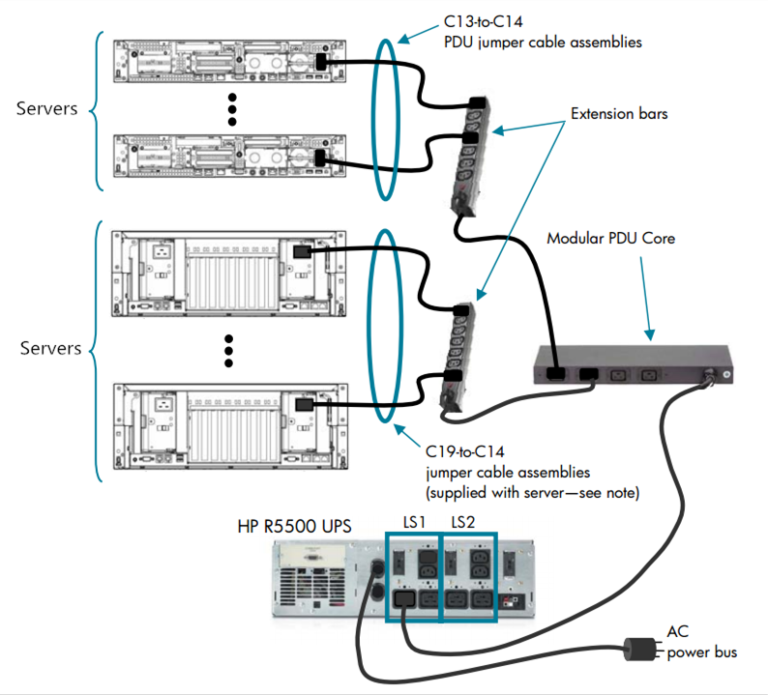
For medium density system, the installation of power cord is a little complex than that of low density system. To achieve an effective power connection, different types and other accessories are may be needed. As the following figure shows, power connections are achieved using modular PDH, extension bars and c13 to c14 power cord assemblies. For server which contains hot-pluggable fans accessible by sliding the chassis out on rails, the power cord connecting to the server must have adequate length and slack to allow chassis movement while staying connected and powered up.

For high density system, the length of power cord can be short since cable movement is less frequent. The following figure shows three kinds of methods to connect enclosures to AC power. The first one in the upper area shows that the c13 to c14 power cord is used to connect a single-supply server to a vertical mount PDU, which is suitable for lower-density installations. The second one in the central area shows the use of C13 x4-to-C20 fixed cord extension bars, which is a recommended method for extreme-density installations using redundant power supplies. The last one shows the use of a C13 x2-to-C20 Y-cable assembly, which is recommended for connecting a server with dual 1200-watt power supplies directly to a PDU core with C19 outlets.
Power cord serves as an important bridge in the network device power supply system. I hope after reading this article, you can have a better understanding of server power cord.
Oznake: power cord, c13 to c14 power cord, nema 5 15p to c13 power cord
komentiraj (0) * ispiši * #
Cabling Solutions for 100G CFP/120G CXP
petak , 02.06.2017.The step for higher capacity and throughput in data centers has never stopped and the 100G/120G Ethernet network has been widely applied. However, it is not an easy job to upgrade existing 10G/40G equipment to meet the requirement of 100G/120G Ethernet network. Is there any cabling solution for smooth migration from 10G/40G to 100G/120G? Of course, there is. This article will take multimode 100G CFP/120G CXP transceiver for example and introduce some cabling solutions to you.
We know that 100G CFP/120G CXP transceiver is designed with 24 fiber MTP/MPO connector interface (10 Tx and 10 Rx with each lane providing 10Gbps, leaving 4 channels unused). Therefore, it is usually used with 24 fiber MTP/MPO cable. The following figure shows that two 100G CFP/120G CXP transceivers are separately plugged into 100G port on two 100G switches. And then the two 100G CFP/120G CXP transceivers can be directly connected by a 24 fiber MTP/MPO trunk cable. This the simplest cabling solution for 100G/120G to 100G/120G connectivity.

By using the 24 fiber MPO to 12 LC duplex harness cable, the 100G/120G to 10G connection can be achieved. However, for the optical link completed by 100G CFP transceiver and ten SFP+ transceivers, there are two LC duplex legs are not used; for 120G to 10G connection, one 120G CXP transceiver and twelve 10G SFP+ transceivers are connected which realize 100% fiber utilization. In this cabling solution, three 10G switch may be needed to satisfied the requirement of at least twelve 10G SFP+ ports. As the following figures shows, 100G CFP/120G CXP transceiver is plugged into 100G port on 100G switch on one side, while ten or twelve 10G SFP+ transceivers are plugged into 10G ports on 10G switches on the other side. Then the 100G CFP/120G CXP transceiver and ten or twelve 10G SFP+ transceivers can be connected by the 24 fiber MPO to 12 LC duplex harness cable. This is also the simplest cabling solution for 100G/120G to 10G connectivity.

With the use of MTP/MPO fiber optic patch panel, 100G to 10G connection can also be reachable. From the figure below we can see that one end of 24 fiber MTP/MPO trunk cable is plugged into 100G CFP transceiver on the 100G switch, while the other end is plugged into MTP ports on the rear of the MTP/MPO fiber optic patch panel. Then the one end of ten LC duplex patch cables are plugged into the LC ports on the front of the MTP/MPO fiber optic patch panel and the other end of cables are connected with ten 10G SFP+ transceivers which are plugged into 10G ports on 10G switches. This cabling solution offers ultimate flexibility in allowing connectivity to any row, rack or shelf. In addition, the MTP/MPO fiber optic patch panel can support up to eight groups of this 100G to 10x10G transmission.

There is a hybrid link for 120G CXP transceiver, 40G QSFP+ transceiver and 10G SFP+ transceiver. We can use the 1×3 MTP/MPO conversion harness cable to connect 120G CXP transceiver on 100G switch and three 40G QSFP+ transceivers on 40G switches. Then another three 40G QSFP+ transceivers on the 40G switches can be connected with the twelve 10G SFP+ transceivers on 10G switches by three 12fiber MTP-LC fanout cables.

As 100G/120G Ethernet network has becomes more and more popular, various types of 100G CFP/120G CXP transceivers are available on the market. This article has illustrated some cabling solutions for migration from 10G/40G to 100G/120G and it is not difficult to find that MTP components are commonly used in these cabling solutions. I hope after reading this article, you can learn something useful.
Oznake: MTP/MPO fiber optic patch panel, 120G CXP, 12fiber MTP-LC fanout cables
komentiraj (0) * ispiši * #
