Fiber Optics Solutions
četvrtak, 02.07.2015.
SFP modules: These Informations You Should Know
As the technology and market of optical transceivers continue to mature, SFP transceivers are now widely used in optical transmission solutions. These SFP modules are hot-swappable, which is highly helpful to designers in the Telecommunication industry. SFP transceiver is one of the most dependable device in optical transmission systems because the designs are based on a multi-source agreement (MSA) and are a pluggable form of SFF. Except these helpful information, here are some things you need to know about SFP transceiver modules.
The Applications of SFP Transceivers
SFP transceivers can support fiber networking standards such as Gigabit Ethernet, Fiber Channel and SONET. They also support a variety of other optical transmission systems as well. A compact and hot-swappable SFP transceiver can be used in all kinds of optical transmissions and telecommunications applications. These SFP Optics will connect a switch, router, or other network device. Most SFP transceivers can be found in popular networking systems such as Wide Area Networks (WANs), Metro Access Network, and Metro Core Network.
Types of SFP Transceivers
SFP transceivers are able to provide an excellent amount of variation to consumers. They have a various different transmitters and receivers types, allowing users to decide on the appropriate SFP transceiver for each link to offer the required optical reach over the available multi-mode fiber (MMF) or single-mode fiber (SMF).

The SFP module is usually offered in five different categories, including T, SX, LX, ZX, and DWDM. Take HP SFP module as example:
- for Copper Networks
JD089B and J8177C: operate on standard Category 5 unshielded twisted-pair copper cabling of link lengths up to 100 m - for multi-mode fiber
J4858C and JD118B: 850 nm, for a maximum of 550 m at 1.25 Gbit/s (gigabit Ethernet) - for single-mode fiber
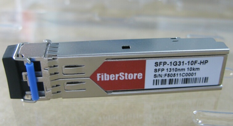
J4859C: 1310 nm, for distances up to 10 km
JD061A and JD062A: 1310 nm, for distances up to 40 km
JD091A and J4860C: 1550 nm, for distances up to 80 km
Each one of these different kinds interface with copper cables and this permits the motherboard to communicate with the unshielded twisted pair (UTP). CWDM cables and single-mode bi-directional fiber optic cables will transmit data both upstream and downstream.
The Benefits of an SFP Transceiver
SFP transceivers are hot-swappable devices, that is to say that these SFP optics are compatible with many other devices including discrete components. They are also compatible to multiple setups across both fiber optic and copper channels. Whether you need both long or short distance communication, SFP transceivers can help.
Digital optical monitoring (DOM) is based upon the new and modern optical transceiver design. Consumers have the ability to monitor real-time parameters of the SFP. Optical inputs and output power, laser bias, and supply voltage will allow designers to monitor real-time.
Do not forget that an SFP cage may be needed for proper operation of the device. It’s usually mounted to the PCB board and will accept the transceiver. It eliminates extra manufacturing steps and reduces costs. SFP transceivers also have a higher optical reliability and will permit higher soldering temperatures. SFP transceivers are recommended by fiber optic component providers to ensure proper data transmission.
Related Recommendation
Fiberstore, the leading manufacturer and supplier of compatible fiber optic transceiver modules, has achieved a breakthrough in HP compatible transceiver modules and successfully commercialized. Not only SFP SX, SFP LX but also 10G SR SFP, 10G LR SFP transceiver, CWDM SFP+ transceiver modules are available now.
Oznake: SFP module, J4858C, J4859C, J8177C, JD118B, 10G LR SFP
petak, 26.06.2015.
Making the Case for 10 Gigabit Ethernet
Several factors make 10GbE implementations a compelling option, including interoperability, cost efficiency, low power consumption, communication quality, and hardware availability. Each of these factors merits careful consideration.
Interoperability Leveraging Existing Technology
During infrastructure upgrades, 10GbE and the TCP/IP protocol are designed to interoperate seamlessly with GbE links, enabling a relatively easy and nondisruptive transition to 10GbE. Two different types of 10GbE connectors are expected to facilitate these links, including 10GBase-T copper and the 10GbE small form-factor pluggable+ (SFP+) interconnect. SFP+ supports different physical port types such as 10GBASE Twinax copper and various types of fiber connections.
By helping ensure that the 10GbE components can cooperatively communicate with GbE devices, switch vendors can deliver interoperability between GbE and 10GbE. Data transitioning from 10GbE to GbE links potentially requires additional buffering on the 10GbE switch to temporarily store the data while it is being transmitted to a low-speed device. In addition, support can be provided for the expected Ethernet standard pause frames (IEEE 802.3x) and priority flow control standards that are part of the enhanced Ethernet standards.
Cost Efficiency Resulting from Fewer Connections
Over time, as 10GbE becomes commonplace, one 10GbE port is expected to be more cost-efficient than multiple GbE ports and Fibre Channel ports. Current GbE storage normally requires multiple ports to provide acceptable storage bandwidth between hosts and arrays. Based on industry best practices for redundancy, a minimum of two connections are used to provide a failover path between host and storage. Additional bandwidth may be required by the application—for example, the performance of sequential data applications such as data warehouses is typically gated by bandwidth. Another best practice is to isolate storage traffic on the SAN from client/server traffic on the LAN, which requires a separate LAN port. Dedicated management ports are often required as well. Just two 10GbE connections (for minimal redundancy) in conjunction with enhanced Ethernet standards such as DCB can handle these requirements while still upholding the best practices just described.
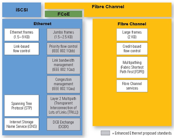
Figure 1. Transitioning to 10GbE with iSCSI, Fibre Channel, and FCoE connections
Low Power Consumption with SFP+ optics
Since the 10GBase-T standard was adopted in 2007 for twisted-pair copper cabling, efforts have been underway to help reduce 10GBase-T power consumption—with a goal of reaching power levels per port that are equivalent to the current 1GBase-T standard. First-generation 10GBase-T adapters have higher wattage demands than their short-reach optical counterparts. Currently, prototype second-generation 10GBase-T implementations are designed to bring wattage demand per port down to reasonable levels.
10GbE SFP+, which today is an early implementation choice for network and storage vendors such as Dell, Cisco, HP, etc. that has very low wattage requirements per port, and SFP+ direct attach copper cable can provide a power-efficient, cost-effective 10 m cabling reach between rack-mounted servers and a top-of-rack switch.
In SFP+ direct attach connections, the module is built into the cables (SFP+ cable). This effort, along with the reduction in the number of separate connections required to manage multiple networks, should help significantly reduce the power requirements of the network.
Communication Quality with Compliant Standards
The Data Center Bridging (DCB) standard is expected to encompass several IEEE 802.1 standards to help ensure communication quality for 10GbE and iSCSI deployments. Priority flow control (802.1Qbb), a link-level flow-control mechanism, is designed to ensure zero loss under congestion in DCB networks. Another standard, 802.1Qau, is intended to provide end-to-end congestion management.
Hardware Availability to Mix GbE and 10GbE
Hardware is available today for mixing GbE and 10GbE. For example, the Dell PowerConnect M8024 blade I/O switch modules can configure ports to run at GbE or 10GbE speeds and provide several options for physical connection types; SFP+ optics use in GbE and 10GbE Ethernet links, such as the Finisar FTLX8571D3BCV 1G/10G Dual-Rate SFP+ optical transceiver over multimode fiber and FTLX1471D3BCV 1G/10G Dual-Rate SFP+ optical transceiver link length up to 10km over singlemode fiber. When used in conjunction with an external 10GbE switch, such as the planned PowerConnect 8024F SFP+ switch, and legacy GbE switches, such as the PowerConnect 6200 series, this hardware is expected to offer several options for configuring iSCSI storage solutions that utilize mixed Ethernet speeds.
Refers to Dell Mixing Gigabit Ethernet and 10 Gigabit Ethernet in a Dedicated SAN Infrastructure
Oznake: Gigabit Ethernet, SFP+ cable, FTLX8571D3BCV, FTLX1471D3BCV
četvrtak, 18.06.2015.
Do Not Miss Fiberstore's 40-Channel DWDM Mux/Demux

DWDM (Dense Wavelength Division Multiplexing), an ideal optical multiplexing technology for long-haul data transporting, can put multiple channels of information using individual wavelength on the same fiber and increase the transmission capacity of optical networks considerably. Currently, DWDM technology is being widely applied in telecommunication networks and becomes the choice of many telecommunication operators.
Since the start of DWDM, various equipment and technologies have been used to enhance the high performance of every part in DWDM network. DWDM Multiplexer and demultiplexer are the main equipment that take charge of the data sources' multiplexing and demultiplexing. In the past years, DWDM multiplexers and demultiplexers have been upgraded rapidly to overcome the insertion loss and to meet the demands of the increasing requests for faster telecommunication, and they are always being combined in one rack by today's vendors also known as DWDM multiplexer.
Fiberstore as a serious manufacture of optical communication published a 40-channel Duplex DWDM Athermal AWG Mux/Demux with competitive features which are described as following:
- Low Insertion Loss: Insertion loss is an inevitable problem in optical networks. Combining LC/UPCconnectors of high quality and AWG technology, this duplex Mux/Demux reduces the insertion loss to a minimum of 3dB and increases the transmission capacity effectively.
- Athermal AWG Technology: With athermal design this mux/demux device is temperature-intensive and allows multiplexing and demultiplexing of DWDM signals over a wide operating temperature range with long-term stability, reliability and large transmission capacity.
- Large Channel Number & Excellent Channel Isolation: This DWDM Mux/Demux is designed for use within the C-band release of DWDM system which uses 40 channels at 100GHz spacing containing the channels from C21 (wavelength: 1560.606 nm) to C60 (wavelength: 1529.553 nm). Also 1.6nm (200 GHz) are available on request. Excellent channel isolation that eases the fiber handling is also provided.
- Space saving: With a standard 19 inch rack mount housing size, this DWDM Mux/Demux saves space effectively.
- High quality and Inexpensive: The products of Fiberstore has been appreciated by customers for its reliable quality. Comparing with other manufactures, Fiberstore offers the lowest price for such a high quality 40-channel DWDM Mux/Demux.
For detailed specifications of this 40 channel DWDM Mux/Demux with Monitor Port, please visit Fiberstore's online shop. Fiberstore currently has 10 of this DWDM Mux/Demux in stock and can deliver on the same day of ordering. Fiberstore also provides custom package to meet customers' requirements.
Originally published at: www.fiber-optic-cable-sale.com
Oznake: 40 Channel DWDM Mux, DWDM Mux/Demux, DWDM
petak, 05.06.2015.
Brief Introduction of PON
What is Passive Optical Networks
A PON is a fiber network that only uses fiber and passive components like splitters and combiners rather than active components like amplifiers, repeaters, or shaping circuits. Such networks cost significantly less than those using active components. The main disadvantage is a shorter range of coverage limited by signal strength. While an active optical network (AON) can cover a range to about 100 km (62 miles), a PON is typically limited to fiber cable runs of up to 20 km (12 miles). PONs also are called fiber to the home (FTTH) networks.
FTTx - Fiber to the x
The term FTTx is used to state how far a fiber run is. FTTx deployments cover varying amounts of that last distance.
- FTTH for fiber to the home
- FTTB for fiber to the building
- FTTC for fiber to the curb or fiber to the cabinet
- FTTN for fiber to the node or fiber to the neighbourhood
- FTTP for fiber to the premises
The typical PON arrangement is a point to multi-point (P2MP) network where a central optical line terminal (OLT) at the service provider’s facility distributes TV or Internet service to as many as 16 to 128 customers per fiber line (see the figure). Optical splitters, passive optical devices that divide a single optical signal into multiple equal but lower-power signals, distribute the signals to users.
In the basic method of operation for downstream distribution on one wavelength of light from OLT to ONU/ONT, all customers receive the same data. The ONU recognizes data targeted at each user. For the upstream from ONU to OLT, a time division multiplex (TDM) technique is used where each user is assigned a timeslot on a different wavelength of light. With this arrangement, the splitters act as power combiners. The upstream transmissions, called burst-mode operations, occur at random as a user needs to send data. The system assigns a slot as needed. Because the TDM method involves multiple users on a single transmission, the upstream data rate is always slower than the downstream rate.
PON is the acronym for Passive Optical Network is a point-to multipoint network. A PON consists of optical line terminal at the service provider’s central office and many number of optical network units near end users. The goal of PON is to reduce the amount of fiber.
There are two standards of PON:
- GPON
- EPON or GEPON
GPON (Gigabit PON) is the evolution of broadband PON (BPON) standard. The protocols used by GPON are ATM, GEM, and Ethernet. It supports higher rates and has more security. GPON uses optical wavelength division multiplexing (WDM) so a single fiber can be used for both downstream and upstream data. A laser on a wavelength (») of 1490 nm transmits downstream data. Upstream data transmits on a wavelength of 1310 nm. If TV is being distributed, a wavelength of 1550 nm is used.
EPON or GEPON (Ethernet PON) is the IEEE standard that uses Ethernet for sending data packets. Based on the Ethernet standard 802.3, EPON 802.3ah specifies a similar passive network with a range of up to 20 km. It uses WDM with the same optical frequencies as GPON and TDMA. The raw line data rate is 1.25 Gbits/s in both the downstream and upstream directions. You will sometimes hear the network referred to as Gigabit Ethernet PON or GEPON.
GPON ONT and EPON ONU Solution
Current and future demands for Internet access bandwidth have led to extensive deployment of FTTH technologies. Of these technologies, GPON and EPON provides the flexibility and cost advantages that service providers need to deliver services profitably to their subscribers. To support the increasing deployment of GPON and EPON in access networks worldwide, Fiberstore has developed full-featured ONT/ONU devices that can deliver a range of services. ONT is located at the customer premise, and ONU is located outside the home. EPON ONU can be working in different temperature and weather conditions. GPON ONT connects the PON to TV sets, telephones, computers, or a wireless router. More information about GPON ONT equipment please visit the fiberstore official website.
Oznake: Pon, GPOM, EPON, EPON ONU, GPON ONT
srijeda, 03.06.2015.
How to Use DOM in Cisco System
Do you know that there is a fiber tester inside your optical transceiver? This "fiber tester" we call it DOM, which is short for Digital Optical Monitoring. DOM is a feature which enables the monitoring of some interesting status values on the interface with the most useful values being the optical receive and transmit powers. You can configure your Cisco (or other brand) device to monitor optical transceivers in the system, either globally or by specified port(s). When this feature is enabled, the system will monitor the temperature and signal power levels for the optical transceivers in the specified port(s). CONSOLE messages and SYSLOG messages are sent when optical operating conditions fall below or rise above the optical transceiver manufacturer’s recommended thresholds. By being able to monitor transmit and receive power levels of optical interfaces you are able to characterize the fiber loss and isolate any unidirectional connectivity issues. So, how to use DOM for your optical transceiver in Cisco system is our main topic today.
DOM allows to monitor some parameters so that network administrators can then check and ensure that the module is functioning correctly. These real-time operating parameters include:
- Optical Tx power
- Optcal Rx power
- Laser bias current
- Temparature
- Transceiver supply voltage
There are some restrictions of using DOM in Cisco system including:
- Ensure that your optical transceiver supports DOM. For Cisco original optical transceivers, you need the transceiver module compatibility information for configuring transceiver monitoring.
- In case of combo ports with SFP and RJ45 provision, when SFP is inserted in slot or port and media type is not configured to SFP, DOM is functional only if global transceiver monitoring is enabled.
- CISCO-ENTITY-SENSOR-MIB traps are sent only once after the threshold violation. However, SYSLOG traps are sent according to the monitoring interval.
| Command or Action | Purpose | |
| Step 1 | enableExample: Router> enable | Enables the privileged EXEC mode.• Enter your password if prompted. |
| Step 2 | configure terminalExample: Router# configure terminal | Enters the global configuration mode. |
| Step 3 | transceiver type allExample: Router(config)# transceiver type all | Enters the transceiver type configuration mode. |
| Step 4 | monitoringExample: Router(config-xcvr-type)# monitoring | Enables monitoring of all optical transceivers. |
| Step 5 | monitoring intervalExample: Router(config-xcvr-type)# monitoring interval 500 | (Optional) Specifies the time interval for monitoring optical transceivers. Valid range is 300 to 3600 seconds, and the default value is 600 seconds. |
In conclusion, there are three main command that can be used to turn on/off DOM for all transceivers type in the system:
- Router(config)#transceiver type all
- Router(config-xcvr-type)#monitoring
- Router(config-xcvr-type)#end
Once enabled, DOM can be accessed via CLI using "show interface transceiver command", shown as the following picture:
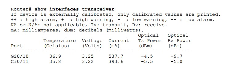
DOM is incredibly handy when troubleshooting fiber issues. A low value in the Rx Power column indicates that you have a bad fiber, or more commonly, a dirty fiber optic patch cable somewhere.
Of all the five values, two mostly used and relevant values are TX and RX power, and temperature is also used sometimes. The operating range of these three values is unique across all modules and is available in the data sheet. Additionally, there is an extension available for this command, which is also very helpful and is used to check threshold values of the above parameters like temperature, Tx and Rx. The command is "show interface gig x/y transceiver detail".
Though DOM is a very helpful functionality of optical transceiver, not all transceivers support DOM in Cisco's optical transceiver products family. For example, the common SFPs, such as the GLC-LX or GLC-SX units that are used by most network engineers on a day to day basis are not with DOM feature.
Why not add this helpful and convenient feature to all transceivers? Actually, Cisco have their own attitude. They think that DOM functionality is worth an extra $300 a pop, putting the cost of a DOM-enabled single mode SFP close to $800. However, DOM functionality is not a novel thing now. Surprisingly, there are some third-party optical transceiver include the DOM functionality but with a low cost. Fiberstore, for instance, as the professional optical transceiver manufacturer and supplier, they can offer Cisco compatible SFP transceivers with DDM or DOM functionality with a low cost. For example, GLC-LX-SM-RGD offered by Fiberstore just at $18.00, GLC-SX-MMD and GLC-LH-SMD at $10.00. But if we want to use non-Cisco transceivers, we need a little different approach to get started with DOM of non-Cisco transceivers. To enable support for non-Cisco SFPs, command "Router(config)#service unsupported-transceiver" is necessary.
Oznake: dom, Digital Optical Monitoring, optical transceiver, cisco
ponedjeljak, 18.05.2015.
SFP Transceiver Signals and Types
Small form-factor pluggable transceiver - Signals
The SFP transceiver holds a Printed track Board that partners with the SFP electronic connector in the service configuration.
Base Transceiver Station
A "base transceiver station" (BTS) is a bit of outfits that eases wireless information exchange amid exploiter out fits (UE) and a network. UEs are implements like protable telephones (handsets), Wireless native loop telephones, computers with wireless Internet connectivity.
The network may be that of whatever of the wireless information exchange applications of tools and methods like GSM, CDMA, wireless native circle, WIFI, WiMAX either different ample zone network (WAN) technics.
BTS is as well referenced to like the broadcast center facility (RBS), point B(in 3G Networks) either, plainly, the center facility (BS). For conversation of the 3GPP Long TERM Evolution normal the shortening EnodeB for developed point B is extensively applied.
Though the expression BTS may be appropriate to whatever of the wireless information exchange norms, it is normally related with portable information exchange applications of tools and methods like GSM and CDMA. In this heed, a BTS forms piece of the center facility self-contained system within larger system (BSS) elaborations for configuration administration. It might as well have outfits for encrypting and decrypting information exchanges, range filtrating implements (band go filters), etcetera. Antenas might as well be deemed like parts of BTS in common feel as they some dissimilar turnaround and dissimilar areas of the cell (in the situation of sectorised center stations). A BTS is managed by a progenitor center facility regulator by way of the center facility command purpose (BCF). The BCF is executed like a separate component either even integrated in a TRX in firm center stations. The BCF delivers a transactions and upkeep (OM) link to the network administration configuration (NMS), and organizes operative states of every one TRX, as well like code managing and alert gathering. The fundamental construction and purposes of the BTS stays the similar notwithstanding of the wireless technologies.
RF module - Transceiver modules
An RF Transceiver component includes either a sender and recipient. The track is characteristically developed aimed at Half-duplex working, though Full twofold components are accessible, characteristically at a developed outlay expected to the appended difficulty.
Small form-factor pluggable transceiver - Types
SFP transmitters and receivers are accessible with a diversity of sender recipient kinds, permitting consumers to choose the suitable transceiver for every one link to supply the needed ocular get to over the accessible ocular fiber sort (e.g. Multi-mode fiber either single-mode fiber). Optical SFP components are normally accessible in some dissimilar categories:
For multi-mode fiber, with black either ecru removal lever
SX - 850nm, for a greatest of 550m at 1.25Gbit/s (Gigabit Ethernet) either 150m at 4.25Gbit/s (Fibre Channel). Related product: 1000BASE SX SFP.
For single-mode fiber, with azure removal lever
- LX - 1310nm, for spaces up to 10km (e.g. Cisco GLC-LX-SM-RGD).
- EX - 1310nm, for spaces up to 40km.
- ZX - 1550nm, for spaces up to 80km.
- EZX - 1550nm, for spaces up to 120km.
- BX - 1490nm/1310nm, Single Fiber Bi-Directional Gigabit SFP Transceivers, matched as "BS-U" and "BS-D" for Uplink and Downlink correspondingly, as well for spaces up to 10km. Variations of bidirectional SFPs are as well produced that employ 1550nm in one management.
- 1550nm 40km (XD), 80km (ZX), 120km (EX either EZX)
- SFSW - Single Fiber Single Wavelength transmitters and receivers, for bi-directional SFPs are a sole fiber. Coupled with CWDM, those duple the flow thickness of fiber ties.
- CWDM and DWDM transmitters and receivers at different wavelengths attaining different greatest distances.
For cuprum twisted couple cabling
1000BASE-T (e.g. GLC-T 1000BASE-T SFP) - those components integrate important circuitry and may solely be applied aimed at Gigabit Ethernet, as that is the user interface they use. They are not harmonious with (or rather: do not have coequals for) Fibre delivery method either SONET.
More related articles about SFP transceiver modules: Optical Transceivers Wiki
Oznake: SFP Transceiver, 1000base-t sfp, GLC-T
petak, 08.05.2015.
Fiberstore 100G CFP and CFP2 Module Solution
Next Generation 100G CFP Modules - CFP2 & CFP4
As 100-Gbps transmission is reaching the field, work is already underway on the second generation of the technology. Upcoming advances will lower costs, increase efficiency, and make 100G applicable to a wider variety of carrier and data center applications. But similar to what has happened in the 10G market, we expect that a different set of optical components will dominate the second and third generation of coherent 100G deployments, where power dissipation, density, and cost are key. Among these optical components, the small form factor pluggable transceiver which supports 100G is one of the essential part, because fiber connectivity in higher-speed active equipment is being condensed and simplified with plug-and-play, hot-swap transceiver miniaturization. And when it comes to providing 100G coherent functionality in a pluggable form factor, CFP and its next generation modules (e.g. 100GBASE-LR4 CFP2) will come to be discussed.
The CFP Multi-Source Agreement (MSA) is currently defining two next generation 100G form factors - CFP2 and CFP4. Compared to the existing CFP form factor, CFP2 and CFP4 will respectively double and quadruple front panel port density. The new form factors take advantage of advances in optics and IC integration, and increase in electrical I/O rate from 10G to 25G. They will support existing and future duplex single-mode fiber (SMF) and parallel multi-mode fiber (MMF) interfaces. The following picture shows the evolution of 100G transceiver modules during 2010 - 2015. Through increasing in front panel density, the next generation of CFP modules will be with a smaller module size and lower power. This is enabled by increased integration of optics and ICs, and by increase in electrical I/O rate from 10G to 25G reducing the I/O width from 10 lanes to 4. In fact, this motivation of immediately taking advantage of advances in integration and I/O technology is similar with the 10G modules.

Evolution of 100G CFP during 2010-2015
CFP2 and CFP4 modules are defined to support existing and future SMF applications. The primary application is 100GE-LR4 10km duplex SMF, with CAUI-4 electrical I/O to be defined in. CFP2 will support 100GE-ER4 40km and 100G DWDM optics when integration technology matures. CFP2 and CFP4 can also support the future 100G structured data center 1000m duplex SMF application. In addition, CFP and CFP2 modules support 100GE-SR10 parallel MMF with CAUI interface. CFP2 and CFP4 modules can also support 100GE-SR10 with CAUI-4 electrical I/O by using a 4:10 Gearbox IC. In fact, an extension of the 100GE-SR10 application is break out of the parallel MMF cable into ten duplex MMF fiber pairs to enable high 10GE-SR front panel density. 10x10G electrical I/O can directly support this functionality. However, CAUI-4 electrical I/O does not support this because it breaks up 10GE lanes into 5G Virtual Lanes. To preserve 10GE lanes, the Optical Internetworking Forum (OIF) is defining a Multi Link Gearbox (MLG) standard which will support 10:4 multiplexing and 4:10 de-multiplexing of ten 10GE asynchronous streams across a 4x25G electrical I/O interface. We can see the differences between CFP, CFP2 and CFP4 in the following picture.
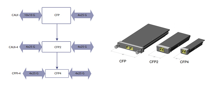
Comparison of CFP, CFP2 and CPF4
Fiberstore Launched the 100G CFP and CFP2 LR4
CFP is widely available in the market, especially with the development of 100G Ethernet in recent years. Fiberstore, the leading manufacturer and supplier of optical communication products, strives to offering the best solution for their customers. Except offering the 100G CFP LR4, they recently announced that they will launch the 100G CFP2 LR4 with high quality and a competitive price. Additionally, it is said that, this CFP2 product can be designed to be compatible with many major brands.
Order Information
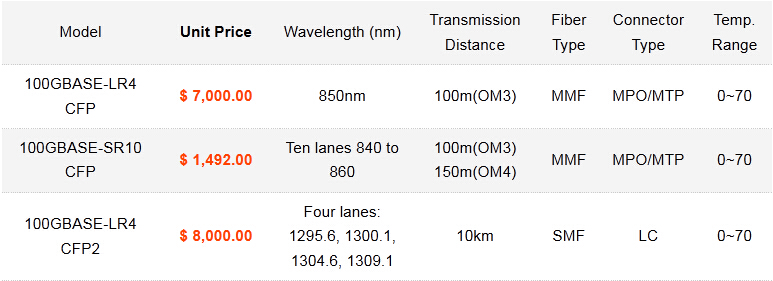
For more information, see: Next Generation 100G CFP Modules – CFP2 & CFP4
Oznake: 100GBASE-LR4 CFP2, 100GBASE-SR10 CFP, 100GBASE-LR4 CFP
utorak, 05.05.2015.
FAQs of SFP modules
Can I use SFP+ optics in SFP ports or use SFP optics in SFP+ ports?
Not all, it's depending on whether the SFP ports accept SFP+ optics (SFP+ 10GBASE Twinax cables and SFP+ modules) or not. However, most (not all) SFP+ ports accept SFP optics. Most 1Gb and 10Gb SFP+ optics only support a single speed (e.g. 10Gb optics can't run at 1Gb). As long as you have a 1Gb SFP at both ends you shouldn't have a problem.
The Summarize of SFP Module
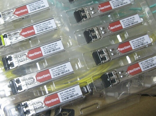
The structure of SFP optical module are: laser, including transmitter and receiver, external fittings are: base, shell, PCBA, unlock pieces, TAB, card buckle, rubber plug, the other to help you identify the convenient, general using the color of the TAB to recognize the parameters of the module type.
According to the rate divided 155M/622M/1.25G/2.125G/4.25G/8G/10G, 155M and 1.25G currently available on the market use more, 10G technologies are maturing, demand positive attitude to rise development is the next major optical module products.
According to the wavelength divided 850nm/1310nm/1550nm/1490nm/1530nm/1610nm, as SFP 850nm wavelength multimode transmission distance 2km less frequent like Cisco GLC-SX-MM; 1310/1550nm wavelength for Single-mode, the transmission distance 2KM above, relatively speaking, these 3 wavelengths lower cost compared to the other.
If you can't know the bare module is simple to confuse the normal distinction between manufacturers will pull rings in color, take CWDM SFP module as an example: black pull ring for multimode wavelength is 850nm; blue wavelength 1310nm module; yellow is the wavelength of 1550nm module; purple is the wavelength of 1490nm module.
Why choose compatible SFP Module
The simple answer to this query (as most other suppliers will explain) is cost, but that's just one of the reasons to purchase a compatible SFP, SFP+ or XFP fiber optic transceiver. For example in a scenario where gigabit speed is required to run across a point-to-point link, the distance between the link length is assessed and an appropriate SFP transceiver module native to the host device is chosen. If a Cisco platform was in situ then the selection of module will be limited by among the following: 550meter (GLC-SX-MMD), 10km (GLC-LH-SMD), 40km (GLC-EX-SMD) or the maximum 70km (GLC-ZX-SMD). Using a compatible SFP you can choose from a variety of distance limits from 550meters up to 100km in numerous increments with distances of 160km being achievable on the top product lines.
Another advantage of use compatible SFP transceivers is the freedom to tailor the transceiver to your individual requirement.
- Custom serial numbers can be added both to the product label and also hard coded to the device itself.
- Customer Logos can be added to the products.
Latches can be color coded for high density link identification Fiberstore also provide a recoding service in China, this specific service means existing SFP's can be adapted if the host device is to be changed. In some instances, even cross-device compatibility is quite possible.
SFP transceiver is a very popular format that’s recommended by a large number of fiber optic component providers. These businesses carry SFP transceivers for those Cisco and HP devices along with transceiver modules for many other manufacturers. Especially, you can find a full product line of our New HP SFP modules, such as J4858C, J4859C, JD118B, and JD092B, etc. Our HP SFP and SFP+ moduels are 100% compatible with a good price and enjoy same-day shipping.
Oznake: SFP module, SFP Transceiver, HP J4859C, Cisco SFP
četvrtak, 30.04.2015.
Underground Wire Locator Overview
When first introduced approximately 40 yearsjavascript:%20void(0); ago, underground wire locator needed to do little more than find buried water, gas, or sewer lines. Today, locating has become more complex as telecommunications wires join utility lines in the underground environment. Surprisingly, though, today's underground wire locator can transmit power across densely populated or areas where land is costly or environmentally or aesthetically sensitive with the same basic tjavascript:%20void(0);echnology.
Most of the time, the wires that you are locating are buried four or five feet underground. You definitely do not want to start digging and risk causing more damage. But you can solve this problem without any damage by using an underground wires locator. What is this underground wire locator composed of?
The underground wire locator or underground wire tracer is a generally consisted of two parts, a hand-held receiver and compact transformer. Both are battery-powered, relatively light and housed in weather-resistant cases. The receiver locates underground lines by detecting magnetic fields created by electrical current passing through cable or tracer wires. Information is displayed in a window at the top of the receiving unit. The receiver unit is all that is needed to locate live electrical cable and in some instances, the receiver alone may be able to locate passive signals of communications wires. While the receiver gets that signal, allowing the locator operator to trace the signal’ s path and follow the cable being located.

The Features of underground wire locator
- Small size, light weight, easy to carry
- Detection method is simple, easy to maintain, with automatic protection function
- Low supply voltage and applicability
- Transmitter power, high efficiency
- Detection error is small, anti-interference ability
- Stable and reliable performance
With its functions of identifying particular wires and their locations, creating an electromagnetic field, setting on a specific frequency, it can detect any interruptions or deviations that could signal a problem. Since you have known its features and functions, you may be curious about how to use it properly.
It is important to make sure to use the wire locator appropriately as it is a delicate procedure when considering that electricity and wiring is involved. Make sure to take the necessary precautions while maintaining the wire locator adequately to avoid misuse and any resultant defects. When you operate the underground wire locator, you should pay attention to the following procedures before operation:
- Purchase a reputable underground wire locator
- Test the voltage power
- Make the necessary tests beforehand
- Follow wire locating procedure
- Continuity testing
For more information about fiber optic testers and tools please visit: Fiber-optic-tutorial.com
Oznake: Underground Wire Locator
srijeda, 29.04.2015.
Muse on 10G SFP modules
As 10Gb SFP+ cables and transceivers have become more common in the current data centers, the issue of vendor lock or encryption might become a problem for data center technicians. This paper discusses the working principle which is used to implement the encryption, why it's employed and the way to overcome it.
2-wire Serial Interface
SFP+ cables and transceivers use a 2-wire serial interface (called I2C) so that the network equipment to poll a specific port and obtain specifics about the cable or transceiver that's connected to that port. This interface can also be known as the Digital Diagnostic Management Interface, Digital Diagnostic Monitoring Interface or DDMI.
The DDMI provides specifics about the cable or transceiver assembly including vendor, serial number, part number, and date of manufacture which is stored in a memory chip or microprocessor inside the cable assembly.
EEPROMs Information
SFP+ passive cables contain EEPROMs inside the connector back shell which have I2C ports. These cables can also be known as SFP+ DAC or SFP+ direct attached Twinax copper cables. An EEPROM is an "Electrically Erasable Programmable Read-Only Memory" chip which is programmed within the factory with precise information about the cable assembly.
SFP+ active copper cables and fiber optic transceivers contain microprocessors inside the connector back shell. The microprocessor has memory which is available to the network through the 2-wire I2C interface. For active cables and transceivers, the interface allows real-time access to device operating parameters and includes alarm and warning signs, which alert the device when particular operating parameters are away from the factory settings.
Ordinarily, these EEPROMs and microprocessors abide by the SFF or Small Form Factor standards, which define the I2C interface protocol and allocate certain information to a particular memory location.
Vendor Lock and Encryption
Some vendors incorporate encryption or "vendor lock" inside their equipment that will issue an alert message if a non-vendor approved cable assembly is plugged into a port. In theory, this makes sure that devices manufacturers will not need to troubleshoot problems due to sub-standard cables. Oftentimes, devices vendors using encryption charge more for their own cords since they lock out use of other cords. In fact, encryption is unnecessary as all reputable manufacturers of SFP+ cables and transceivers meet the standards that IEEE and SFF have founded for SFP+ and interoperability isn't important. Most network equipment vendors that employ encryption allow a work around as long as the customer acknowledges the warning. As an example, the customer might have to acknowledge that he understands the warning and he can accept it before moving on.
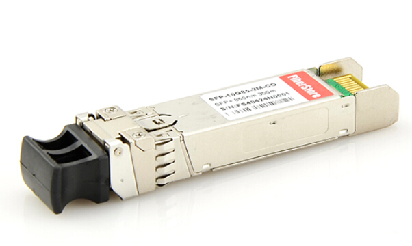
Fiberstore’s Cisco Compatible SFP+ Cables Solution
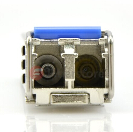
Fiberstore is a professional OEM manufacturer and supplier of Cisco compatible SFP+ cables. Fiberstore has offered industry standard SFP+ cables for many years that have been tested by the UNH Interoperability lab and confirmed to be compatible with Cisco and equipment from other major vendors. The following figure shows 10G SR SFP+ 850nm module:
Compatible SFP+ Cable Part Numbers
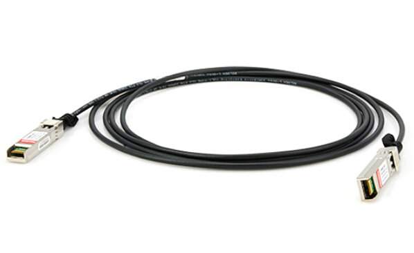
- SFP-H10GB-CU1M 1 meter (3 ft), Wire AWG = 30, SFP+ Passive Copper Cable Assembly, Double-ended
- SFP-H10GB-CU1-5M 1.5 meter (5ft), Wire AWG = 30, SFP+ Passive Copper Cable Assembly, Double-ended
- SFP-H10GB-CU2M 2 meters (6.5 ft), Wire AWG = 30, SFP+ Passive Copper Cable Assembly, Double-ended
- SFP-H10GB-CU2.5M 2.5 meters (8ft), Wire AWG = 30,SFP+ Passive Copper Cable Assembly, Double-ended
- SFP-H10GB-CU3M 3 meters (9ft), Wire AWG = 30, SFP+ Passive Copper Cable Assembly, Double-ended
- SFP-H10GB-CU5M 5 meters (16ft), Wire AWG = 24, SFP+ Passive Copper Cable Assembly, Double-ended
Fiberstore’s Cisco compatible SFP+ passive copper cables use proprietary encryption within the assembly’s EEPROM to prevent the warning messages that Cisco equipment may produce when non-Cisco approved cables are plugged in. This enables data center designers to prevent unwarranted concern which may be related to startups when the users see these warning messages. Fiberstore’s cables meet the industry standards for SFP+ cables and are offered in the same lengths and wire gauges as Cisco DAC assemblies, but at a significant cost reduction.
Oznake: SFP+ cable, optical transceiver, 10g sfp module

| < | srpanj, 2015 | |||||
| P | U | S | Č | P | S | N |
| 1 | 2 | 3 | 4 | 5 | ||
| 6 | 7 | 8 | 9 | 10 | 11 | 12 |
| 13 | 14 | 15 | 16 | 17 | 18 | 19 |
| 20 | 21 | 22 | 23 | 24 | 25 | 26 |
| 27 | 28 | 29 | 30 | 31 | ||
Srpanj 2015 (1)
Lipanj 2015 (4)
Svibanj 2015 (3)
Travanj 2015 (13)
Ožujak 2015 (10)
Veljača 2015 (8)
Siječanj 2015 (9)
Prosinac 2014 (4)
Dnevnik.hr
Gol.hr
Zadovoljna.hr
Novaplus.hr
NovaTV.hr
DomaTV.hr
Mojamini.tv
About Me
Ima Blogger, Just Share Various Fiber Optic Telecom Network Topics, Information, News, Questions, Sources and Network Solutions.