Marketing
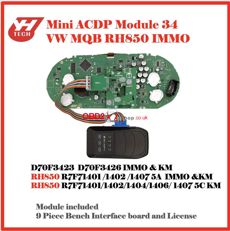
Yanhua Mini ACDP Module 34 VW MQB RH850 Installation Tutorial
This is a tutorial on how to install Yanhua Mini ACDP Module 34 for VW MQB RH850 IMMO programming. Need to work with Mini ACDP-2 or Mini ACDP-1. It included a 9-piece bench interface board and license.
Features
Support D70F3423, D70F3426 IMMO & KM;
Support RH850 R7F71401/1402/1407 5A IMMO & KM;
Support RH850 R7F71401/ 1402/ 1404/ 1406/ 1407 5C KM.
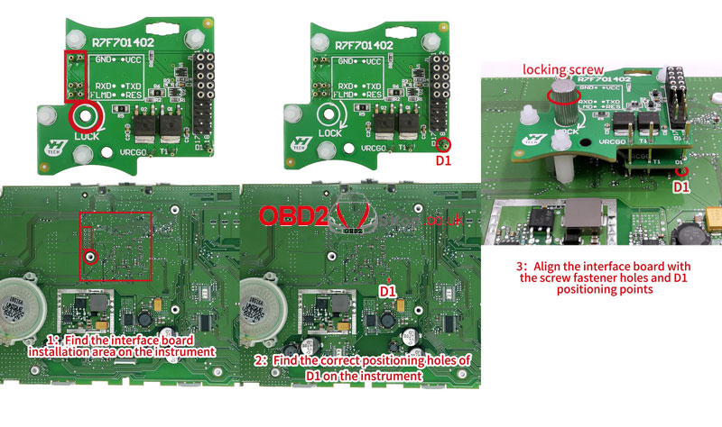
Thumb Screw-Fastened R7F701402 Interface Board
1. Follow the visual positioning mark on the Module 34 Interface Board to find the installation area on the instrument.
2. Find the correct positioning holes of D1 on the instrument.
3. Align the interface board with the screw fastener holes and D1 positioning points.
4. Press the interface board down and tighten the locking screw.
5. Confirm again that the interface board D1 positioning pins are completely aligned with the D1 positioning holes of the instrument.
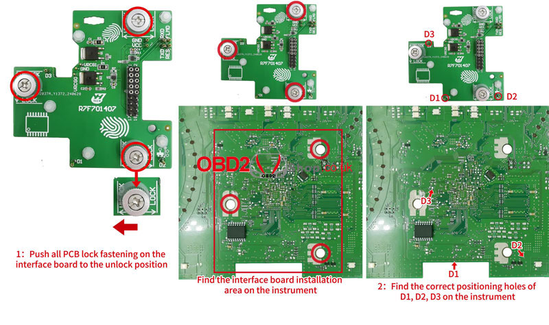
Lock Fastening R7F701407 Interface Board
1. Push all PCB lock fastening on the interface board to the unlock position. Follow the visual positioning mark to find the installation area on the instrument.
2. Find the correct positioning holes of D1, D2, D3 on the instrument.
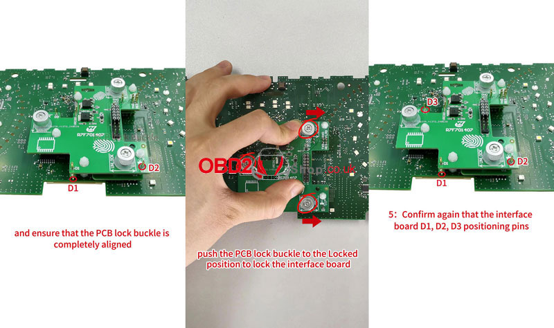
3. Check that the D1 and D2 positioning pins are completely aligned with the positioning holes of the instrument. Ensure that the PCB lock buckle is completely aligned.
4. Finger down the pressure interface board, and push the PCB buckle to the locked position to lock the interface board.
5. Confirm again that the interface board D1, D2, and D3 positioning pins are completely aligned with the positioning holes of the instrument.
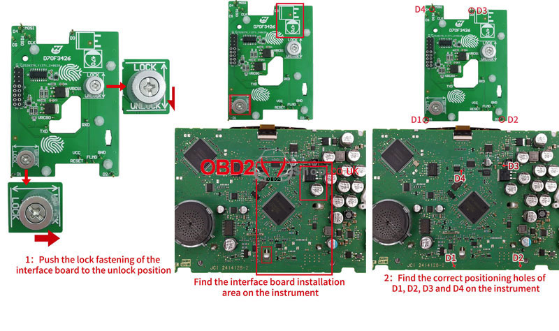
Lock Fastening D70F3426 Interface Board
1. Push the lock fastening of the interface board to the unlock position. Find the interface board installation area on the instrument according to the visual positioning mark on the interface board.
2. Find the correct positioning holes of D1, D2, D3 on the instrument.
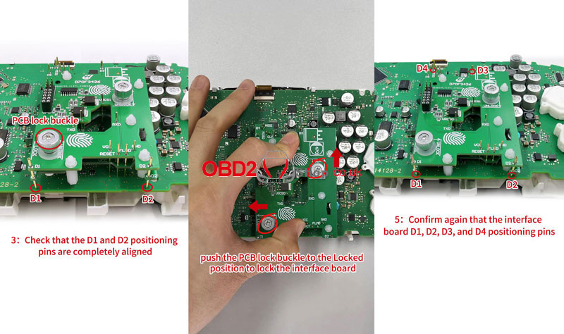
3. Check that the D1 and D2 positioning pins are completely aligned with the positioning holes of the instrument. Ensure that the PCB lock buckle is completely aligned.
4. Push the PCB lock buckle to the locked position to lock the interface board.
5. Confirm again that the interface board D1, D2, D3, and D4 positioning pins are completely aligned with the positioning holes of the instrument.
www.obd2shop.co.uk
Post je objavljen 24.07.2024. u 08:49 sati.