How to Make the Ethernet Patch Cable at an Exact Length?
četvrtak , 29.12.2016.Are the Ethernet patch cables you purchase from the local or online stores always at the proper length? Or not so suitable for your network because they are too long or too short that don’t meet your expectations? Have you ever considered making the improper Ethernet patch cable into a suitable one by yourself, so that you can deploy your network by using you own Ethernet patch cable and save a lot of money, time and space? In fact, terminating the Ethernet patch cables is not so difficult but very useful for fast network deployment, which will be presented in the post. Meanwhile, there are several important things you should take into consideration before making the Ethernet patch cable termination, which will be also illustrated in details. Hope these information will guide you to make your own Ethernet patch cable and then deploy your Ethernet network in a very fast, smooth and cost effective manner.
Selecting a Proper Ethernet Patch Cable
Before making the Ethernet patch cable termination, you should choose one kind of Ethernet patch cable which is most suitable for your network, since there are various kinds of Ethernet patch cables available on the market, such as, cat5, cat5e, cat6, cat6a, cat7, etc. Considering that cat5e, cat6 and cat7 patch cable are the most commonly used ones at present, both of which will be introduced the following text.
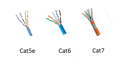
As an upgrade version of cat5 patch cable, cat5e patch cable has the ability to support gigabit speed, allowing for a faster, more reliable and steady network. It is much commonly used in home and office applications. As for cat6 patch cable, it is an enhanced version of cat5e patch cable that has much more sophisticated structure, as shown in the above figure. It is an ideal solution to face future-proof network that supports the transmission speed up to 10 gigabit with a long transmission distance. In contrast to cat5e and cat6 patch cable, cat7 patch cable is a kind of shielded Ethernet cable that has a great improvement in the capacity and reliability. It is more expensive since it has been the most durable and longer-lifespan Ethernet patch cable at present. As for the structural differences among cat5e, cat6 and cat7 patch cable, it is very easy to learn from the above figure.
Choosing a Proper Wiring Scheme
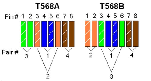
In general, there are two common wiring schemes, T568A and T568B, which are designed to specify the arrangement of the colored wires for terminating the Ethernet patch cable. That’s to say, if you want to terminate your cable, you should arrange the colored wires in a correct order according to the standard of T568A or T568B, as shown in the following figure. As for their applications, T568A is always applied in home-networking connections, while T568B is strongly suggested for the preexisting residential network wiring or other similar projects.
Terminating the Ethernet Patch Cable You Need
There are ten detailed steps to make the Ethernet patch cable you need at an exact length, which will be presented below. Terminating the cable you need according to the following step-by- step procedures can ensure the performance of the DIY cable and the stability of your network.
a. Prepare the essential tools and materials for the cable termination, including some RJ45 connectors, a pair of wire scissors or wire strippers, a spool of Ethernet cable, a RJ45 crimping tool and a network cable tester.
b. Use the wire scissors or wire strippers to cut the Ethernet patch cable you need into a desirable one with the exact length. Besides, you’d better to add two or three inches extra no matter how long you want the Ethernet patch cable to be, for the sake of messing up.
c. Utilize the RJ45 crimping tool to shove the sheath of the cable (about 1 inch) from the end of the cable into the stripper, and lightly squeeze the crimping tool.
d. When the razors slice of the crimping tool pass through the cable jacket, you should twist the cable and pop off the cut end of jacket.
e. Once the jacket is stripped, you can see four twisted pairs of wires with four different colors. You should separate these four pairs of wires into eight individual wires and rearrange them into sequence according to the color order in T568A or T568B.
f. Cut the tips of the wires in order to match with the RJ45 connector. Then guide the wires into the plug and slip them into their own channels. The ends of the wires should reach as far as possible toward the front edge of the plug.
g. Double check and confirm whether the wires are in sequence according to the right order or not, avoiding error connection.
h. Insert the plug into the crimping slot of the crimping tool and squeeze the crimping tool to make the pins inside the plug into the wires and fasten the plug onto the cable. Hence, the RJ45 connector can be a permanent part of the new cable.
i. As for the other end of the cable, just terminate it in the same way, so that you can finish the whole termination process for your own Ethernet patch cable.
j. Test the cable by a network cable tester to confirm that it really works. In addition, if it doesn’t work, you are highly suggested to check the color order of the wires first.
Conclusion
Before making your own Ethernet patch cable, you should choose a proper Ethernet patch cable and a wiring scheme according to your network requires. As for the process of making the cable with an exact length, it is not so difficult as you consider, but easy and fast. The only thing that deserves a bit of attention is to be careful in the whole termination process, so that the Ethernet patch cable can be made at a proper length and work with your network like a charm.
komentiraj (0) * ispiši * #
An In-Depth Look at Mode Conditioning Patch Cable
četvrtak , 22.12.2016.As we all know, fiber optic cable jumper plays an important role in Ethernet network connection, which becomes more and more diversified to satisfy the different connection requirements in recent years. For instance, standard fiber patch cable like single mode patch cable and multimode patch cable, special fiber patch cable like mode conditioning patch cable and bend insensitive patch cable, etc. Among these various fiber patch cables, mode conditioning patch cable has been one of the most popularly used fiber patch cable due to its unique features and advantages, which will be introduced in the following text.
What Is Mode Conditioning Fiber Patch Cable?
Mode conditioning patch cable is a special kind of duplex fiber patch cable that consists of two fibers, a conditioned fiber and a non-conditioned fiber, capped at either end with connectors. In the conditioned fiber, a single mode fiber and a multimode fiber are fusion spliced in an offset manner, with a precise core alignment and angle, protected by a black over-wrap. While in the non-conditioned fiber, there is only a length of multimode fiber. To get a better understand of its structure, you can take the following figure as reference.
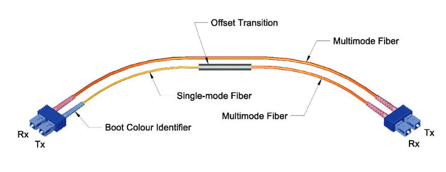
As shown in the figure above, there are two multimode fibers in one end, and a multimode and single mode fiber in the opposite end. The end with two multimode fibers is designed to connect the cable plant, while the other end connects to the transceiver equipment with the single-mode leg linking to the transmit side. Hence, light signal can be launched on to the multimode fiber in the conditioned one at a specific angle, giving the patch cable its mode conditioning property. Besides, it is worth mentioning that this kind of fiber optic cable is fully compliant with IEEE 802.3z application standards.
Why Mode Conditioning Cable Is Used?
As far as our information goes, 1310nm long wave signal is always transmitted through single mode patch cable for 1000BASE-LX transmission as a cost effective solution. However, if the mentioned above transmission utilizes multimode patch cable, it will cause a phenomenon known as DMD (differential mode delay). In simple words, if the same signal is carried to a multimode patch cable, there will be multiple signals created in the multimode patch cable that may make transmission errors to some extent.
In order to solve this problem, mode conditioning patch cable is put forward that utilizes an offset between the single-mode fiber and multimode fiber to eliminate transmission errors, allowing for 1000BASE-LX signal transmission through multimode patch cable. For example, when 1000BASE-LX routers and switches are installed into existing multimode cable plants, mode conditioning patch cable is highly recommended to adapt the single-mode output of 1000BASE-LX transceivers to a multimode cable network.
Notices for Using Mode Conditioning Patch Cable
After knowing the feature and advantage of mode conditioning patch cable, do you also consider using mode conditioning patch cable to finish the conversion from single mode to multimode? Here are some notices for you so as to use the mode conditioning patch cable in a proper way.
Mode conditioning patch cable should be used in pairs to finish the conversion. That’s to say, most orders for this kind of fiber optic cable are always in even numbers. If there is an odd number order, the single one must be used for standby application or replacement.
Mode conditioning patch cable is only able to convert single-mode transmission to multimode transmission. If the conversion from multimode to single-mode is required, you are suggested to choose a media converter as an easy and cost effective solution.
Please check and confirm the connector of your switch before application. If it is equipped with SC or LC connectors, you should connect the yellow leg (single-mode) of the cable to the transmit side and the orange leg (multimode) to the receive side of the equipment. It is imperative that this configuration should be maintained on both ends.
Conclusion
Mode conditioning patch cable enables the conversion from single-mode to multimode with the feature of fusion splicing between single mode fiber and multimode fiber. After knowing its feature and advantage, if you want to choose this kind of cable to finish the conversion in your network, you can order it from FS.COM. It is no doubt that there are various mode conditioning patch cables with different connectors available. Besides, if you cannot find one to meet you requirement, you can also order custom fiber patch cables for your network.
komentiraj (0) * ispiši * #
LC Interface or MTP/MPO Interface for 40G QSFP+ Module
petak , 16.12.2016.As we know, duplex LC interfaces are widely used in 10G SFP modules, for instance, SFP-10G-LR-S module and SFP-10G-SR module, which occupy the majority of 10G module market. However, for 40G QSFP+ modules, both LC interface and MTP/MPO interface play important roles in meeting the high speed transmission, which are available on 40G QSFP module market. What are the differences between these two interface types? Which one should be chosen when deploying 40G Ethernet network? Do they function similarly in the same application? Let’s talk about this topics and find one kind of 40G QSFP+ module with the most suitable interface type so as to make a smooth 40G connection for our network.
Differences Between LC Interface and MTP/MPO Interface
From the following figure, we can see the examples of QSFP+ modules with two different interfaces. The left one is the module with with LC interface, while the right one is with MTP/MPO interface. The differences between these two kinds of modules vary from the fiber types they work with to the working principles, which will be analyzed in the following text.
Different Fiber Types
As for the QSFP+ module designed with LC interface, it usually works with single mode fiber (SMF). Since SMF is able to support 40G network for a very long distance, the LC interface module is widely applied in long transmission. However, the QSFP+ module with MTP/MPO interface design is strongly recommended in the short distance application where the 40G signals are transmitted through multimode fiber (MMF). What should be paid attention to are some special QSFP+ modules, like QSFP-40G-PLRL4 and QSFP-40G-PLR4 module, which don’t fit the rule. Although the two kinds of modules mentioned above are designed with MTP/MPO interfaces, they are also capable of supporting 40G long distance transmission through SMF.
Different Working Principles
As shown in the following figure, QSFP+ module with LC interface has a very complicated working principle for transmitting 40G signals. At the beginning of the transmission, four 10G serial data signals via four channels are transmitted to laser drivers in the transmitting side. Then they are directly controlled by the laser drivers as four modulated lasers (DML) with different wavelengths. After that, the output of four DMLs are optically multiplexed as a total 40G optical signal and transmitted through the LC connector and the SMF. While in its receiving side, the 40G optical signal is demultiplexed into four individual 10G signals with different wavelengths, then collected by the discrete photo diode, and finally amplified by the TIA and outputted as electric data.

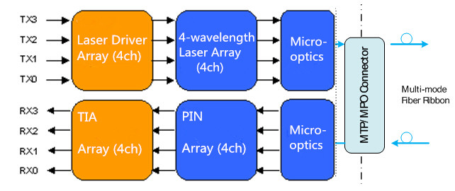
As for QSFP+ module with MTP/MPO interface, its working principle is much easier than the previous one as it doesn’t require CWDM technology. In its working process, the transmitter firstly converts four 10G parallel electrical input signals into parallel optical signals by using the laser array. Then the four 10G parallel optical signals are directly transmitted through the MMF ribbon in a parallel mode. Finally, these parallel optical signals are transmitted through the photo detector array and converted into parallel electrical output signals in the receiving side. To better understand the working principle, here offers the figure of its detailed working process.
Besides, the mentioned above QSFP+ module with MTP/MPO interface, like QSFP-40G-PLRL4 and QSFP-40G-PLR4, also works in a parallel mode that features four independent transmitting and receiving channels to finish 10G operations, achieving a whole 40G connection. The only difference of the working principle is that the signals are transmitted and received through eight SMF ribbons, hence this kind of module can also achieve a long distance transmission.
Conclusion
From this article, we can easily find that QSFP+ module with LC interface is more commonly used for long distance application, while QSFP+ module with MTP/MPO interface is a cost effective solution for short distance application. Except that, there is still a great difference for applications between the two kinds of modules due to their different working principle. As QSFP+ module with LC interface uses CWDM technology to transmit signals with different wavelengths through a pair of single mode fibers, the 40G signals can’t be separated into four 10G signals and transmitted to 10G devices. However, QSFP+ module with MTP/MPO interface can be used in the 40G to 10G application by using an external 12-fiber parallel to 2-fiber duplex breakout cable.
komentiraj (0) * ispiši * #
How to Install 40G QSFP+ Transceiver for Your Network?
srijeda , 14.12.2016.With the continuously growing demand for higher capacity and bandwidth, the deployment of 40G Ethernet network becomes much more necessary than ever before. As one of the key components to accomplish a whole 40G connection, QSFP+ transceiver, a compact, hot-pluggable module, is designed with four independent channels to transmit and receive 10G signals, supporting 4x10 Gbit/s data rates. This kind of module can be used both in 40G to 40G application where one QSFP+ transceiver will be connected to another QSFP+ transceiver and in 10G to 40G application where one QSFP+ transceiver will be connected to four SFP+ transceivers.
Do you also want to upgrade your system from 10G to 40G Ethernet network by using QSFP+ transceiver? The following will detailedly describe the step-by-step procedures for installing QSFP+ transceiver and attaching optical network cable to the transceiver, which will be helpful for you to achieve a fast, smooth and seamless 40G network deployment.
QSFP+ Transceiver Installation
Before installing QSFP+ transceiver, three tools should be prepared for the 40G migration. One is the wrist strap or other grounding device with the function of avoiding ESD (electro-static discharge) occurrence. Another is the antistatic mat or antistatic foam, capable of setting the transceiver on. The other is the equipment for fiber-optic end-face cleaning and inspection. All of these tools are indispensable for making a secure and smooth installation.
After that, you can start to install the QSFP+ transceiver according to the following procedures. Considering that there is either a pull-tab latch or a bail-clasp latch in QSFP+ transceiver, the procedures for both types will be listed below.
a. Put the ESD wrist strap on and attach the other end of the ESD wrist strap to a properly grounded point on the chassis or the rack.
b. Get the QSFP+ transceiver by removing its protective packaging.
c. Check the QSFP+ transceiver label and confirm whether the type of the module is suitable for your network or not.
d. Remove the optical bore dust plug from the transceiver and store it in a clean place, therefore it can be easily found and fast used next time.
e. Since there are two kinds of latches for the transceivers, they should be connected to your network in different ways. As for the transceiver with a pull-tab latch, you should hold it to ensure the identifier label is on the top. As for another transceiver, you should keep its bail-clasp aligned in a vertical position (see the following figure).
f. Then align and slide the transceiver to the module socket carefully until it contact with the socket electrical connector.
g. Press firmly on the front of the QSFP+ transceiver with your thumb to fully seat the transceiver in the module socket.
h. Reinstall the dust plug into the transceiver optical bore before attaching the optical network cable to the transceiver.
Optical Network Cable Attachment
After installing the QSFP+ transceiver, you should attach the optical network cable to the transceiver to finish the whole 40G transmission. But how to attach the optical network cable? What should be paid attention to in the attaching procedures? The following will talk about this topic and give you answers.
Before making the 40G connection, you should ensure that the unplugged optical network cable connectors and the transceiver optical bore are protected by the dust plugs. Meanwhile, you should also check and clean the MPO connector or duplex LC connector end faces. Besides, you can only grasp the connector housing to plug or unplug the optical network cable. Once these points are confirmed, you can attach the optical network cable to your network.
The procedures for attaching the optical network cable to the transceiver are shown below.
a. Remove the dust plugs from the optical network interface cable connectors and the QSFP+ transceiver module optical bores. Also, keep the dust plugs in a clean place.
b. Check and clean the connector end faces of the optical network interface cable.
c. Immediately attach the optical network interface cable connector to the QSFP+ transceiver.
d. Pull slightly on the cable connector boot to check whether the optical network cable is fully seated. If not, please reattach it and make it seated.
Conclusion
From this paper, it can be easily learned to install the 40G QSFP+ transceivers and attach the optical network cables to the QSFP+ transceivers, hence the 40G connection can be smoothly finished in a correct way. Using the methods mentioned above to upgrading your network can protect the QSFP+ transceivers from being damaged and keep a stable performance for the 40G connection.
komentiraj (0) * ispiši * #
Selecting Proper Fibers for Smooth 40/100G Migration
petak , 09.12.2016.Nowadays, there is a widespread concern over the migration from traditional 10G to 40/100G Ethernet network, which seems to be an irreversible trend. As we know, 40/100G Ethernet network can greatly address the problem of very low network speed. Do you also consider upgrading your system for higher bandwidth and larger capacity? There is no doubt that fiber cables must be the first choice for a smooth 40/100G migration, which almost makes copper cables obsolete. But which kind of fiber should be chosen? Is there any key notice should be taken into consideration when selecting fiber for the migration? These problems will be explored and answered in the following parts.
Which Fiber Type Should Be Chosen for 40/100G Migration?
It is reported that over 80% of data centers support their network within 100 meters in recent years. That’s to say, if the fiber has the ability to transmit 40/100G signal for a short distance, it almost satisfies the needs for migration. In general, there are single mode and multimode fiber available for data centers, both of which are capable of supporting 40/100G data transmission links. But which one is the most cost effective for a whole 40/100G system? Let’s talk about it and seek the answer.
For single mode fiber, it can only carry a single light signal and has little modal dispersion in the transmission process, which is highly recommended for long distance transmission. While for multimode fiber, it is able to carry several light signals in the different modes that results in serious dispersion. What’s more, the longer the signals are transmitted, the larger the dispersion will be. Hence, multimode fiber is more popularly used in short distance transmission and much more inexpensive than single mode fiber.
In short, although single mode fiber has a higher performance in data transmission, multimode fiber is more suitable for 40/100G migration as the most cost effective fiber solution.
Notices for Data Transmission Distance
There are two kinds of multimode fiber patch cables, OM3 patch cable and OM4 patch cable that allow for smooth 40/100G migrations with different transmission distances. The following figure shows some commonly used transmission cases in 10G, 40G and 100G network, both of which are able to use short--wavelength (850 nanometer) transmission over OM3 and OM4 patch cable.
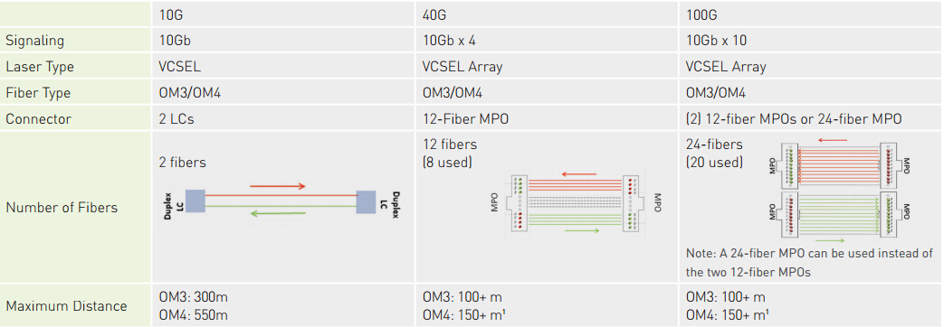
From the figure, we can easily learn that both OM3 and OM4 patch cable are suitable for 10G, 40G and 100G applications. As for OM3 patch cable, it is able to support 10G network at lengths up to 300 meters and 40/100G network at lengths up to 100 meters. Compared to OM3 patch cable, OM4 patch cable can transmit signals longer under the same network, which is also a little bit expensive. In fact, its transmission distance can be 550 meters in 10G network and 150 meters in 40/100G network.
Notices for Channel Insertion Loss
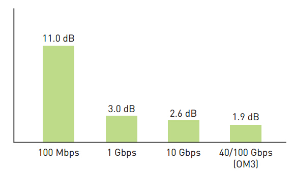
It is obvious that different cables have different channel insertion loss in 40/100G network, which may have different influences on the signal transmissions. Once the channel insertion loss is high, it may cause a failed or wrong signal transmission. So that, the channel insertion loss should be also noticed when selecting fibers.
As shown in the following figure, the channel insertion loss by using OM3 patch cable is about 1.9 dB in supporting 40/100G data transmission link which is much lower than in supporting 10G link. If OM4 patch cable is selected to transmit 40/100G signals, the channel insertion loss is only 1.5dB. Undoubtedly, OM4 patch cable performs better than OM3 patch cable in this aspect.
Conclusion
Are you ready to make the 40/100G migration? If yes, you are suggested to choose multimode fiber as the most cost efficient fiber solution. According to the data transmission distance, you can choose OM3 patch cable to support 40/100G link at length up to 100 meters, which is more inexpensive than OM4 patch cable. If the distance can’t meet your requirement, you are suggest to choose OM4 patch cable with lower channel insertion loss.
komentiraj (0) * ispiši * #
MPO/MTP Cassette Solution for High Density Data Centers
četvrtak , 08.12.2016.To face the challenge of migration from 10G to 40/100G Ethernet network, the fiber technology for higher data transmission speed has developed in a really fast manner. Under this trend, a series of high density fiber equipment, especially MPO/MTP products, are designed to control the costs, by way of maximizing return on assets. Have you ever known about MPO/MTP products, for instance, MPO/MTP cable, MPO/MTP cassette and MPO/MTP patch panel, which are very popularly used in recently years? Among these high density products, MPO/MTP cassette plays an indispensable role in 10G to 40/100G migration, as one of the ideal solutions for high density data centers. The following will mainly introduce the basic information of MPO/MTP cassette and illustrate how it is used for 10G network and the upgrading from 10G to 40/100G network.
MPO/MTP Cassette—Ideal Solution for High Density Fiber Cabling System
MPO/MTP cassette is a modular module that offers secure and smooth transition between MPO/MTP and LC or SC discrete connectors, achieving a better management on the high density fiber cabling system. It is always loaded with 12 or 24 fibers, with LC or SC adapters on the front side and MPO/MTP adapters at the rear, which enables user to take the fibers brought by a trunk cable and distribute them to duplex cable.
At present, there are two types of MPO/MTP cassettes available, LGX MPO/MTP cassette and HD MPO/MTP cassette, both of which have the advantage of scalability to increase density for optimum serviceability and manageability if the data center requires. Besides, there is a special kind of cassette designed with TAP port, which can be used to easily access and monitor the data.
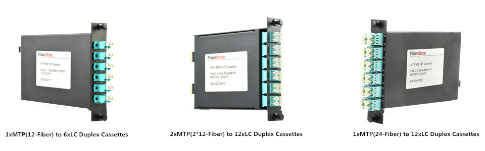
Three Commonly Used MPO/MTP Cassettes
As we all know, the most widely used interface of 10G optics is LC connector. Accordingly, the commonly used MPO/MTP cassettes are MTP-LC cassettes that feature optimized performance and superior optical and mechanical properties. The following figure will show three MTP-LC cassettes, 1xMTP(12-Fiber) to 6xLC duplex cassette, 2xMTP(2*12-Fiber) to 12xLC duplex cassette and 1xMTP(24-Fiber) to 12xLC duplex cassette, with specific port configurations. Both of them can be used for 10G network and the application from 10G to 40/100G.
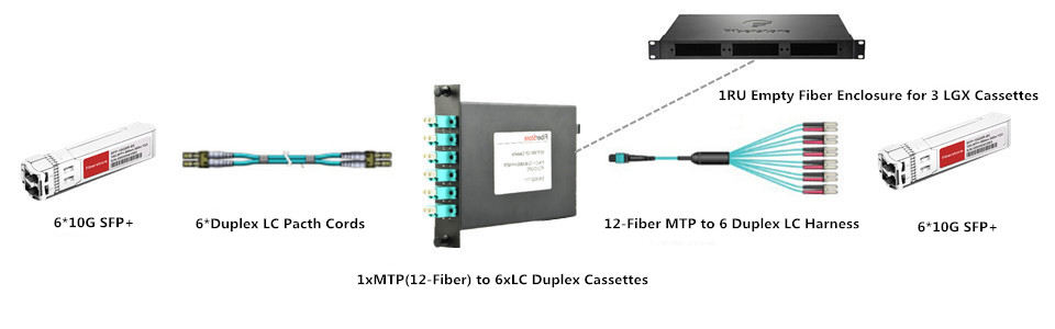
MPO/MTP Cassette for 10G to 10G Application
MPO/MTP cassette can be used for 10G network, with the function of connecting one 10G device to another one. It is generally known that a duplex LC fiber patch cable can be chosen for direct connection if the two 10G devices only need to be connected for a short distance transmission. However, once long distance transmission is required between the two devices, a MPO/MTP cassette would be a good choice for this 10G interconnection or cross connection. In the following figure, it gives an example of a 1xMTP(12-Fiber) to 6xLC duplex cassette used for 10G long distance transmission.
MPO/MTP Cassette for 10G to 40G Application
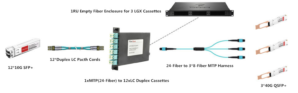
It is highly suggested to use a MPO/MTP cassette to connect 10G device to 40G device, as an optimal solution. Similarly, if the distance is very short between the 10G device and the 40G device, a MTP-4 duplex LC fiber patch cable can be used for direct connection. But when long distance connection is needed, this method can’t meet the requirement any more and a MPO/MTP cassette is strongly recommended for this interconnection or cross connection. The following figure also presents an example of 1xMTP(24-Fiber) to 12xLC duplex cassette for 10G to 40G connection.
MPO/MTP Cassette for 10G to 100G Application
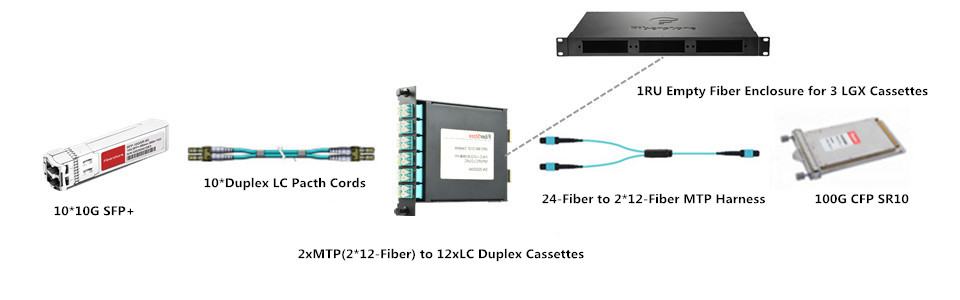
From the following figure, we can learn a 2xMTP(2*12-Fiber) to 12xLC duplex cassette is used for the 10G to 100G application. Is there any point we should note in the upgrading? Of course, a MTP-10 duplex LC fiber patch cable can simply address the upgrading for direct connection if the 10G device is not far from the 100G device. But when the distance between the devices is very long, the MPO/MTP cassette is also very essential for the 10G to 100G application.
Conclusion
MPO/MTP cassette enables fast deployment of high density data center infrastructure that also allows for improved troubleshooting and reconfiguration during moves, adds and changes. At present, there are three most commonly MPO/MTP cassettes, 1xMTP(12-Fiber) to 6xLC duplex cassette, 2xMTP(2*12-Fiber) to 12xLC duplex cassette and 1xMTP(24-Fiber) to 12xLC duplex cassette, both of which are able to support 10G network and the upgrading from 10G to 40/100G.
komentiraj (0) * ispiši * #
Solutions for 40G Short Distance Transmission
četvrtak , 01.12.2016.It is well known that SFP+ transceivers like SFP-10G-SR and SFP-10G-SR-S are very commonly used and perform greatly in 10G short distance transmission. When higher bandwidth is required, several SFP+ transceivers can be used together to offer multiple 10G links as a common solution. However, if an individual 40G link is implemented in this case, it has the ability to perform higher with much faster data transmission rate than multiple 10G links. As the deployment of 40G Ethernet network is not so simple as that of 10G Ethernet network, the following will introduce three widely applied solutions for short distance transmission in 40G Ethernet network which can be useful for you to deploy individual 40G link instead of multiple 10G links.
Three Solutions to Support 40G Short Distance Transmission
With the popularity of 40G Ethernet network, 40G solutions, especially 40G QSFP+ modules, have been widely applied to finish 40G data transmission. At present, there are various kinds of 40G solutions available on the market, which are designed to support different applications. For 40G short distance application, three widely applied solutions, QSFP-40G-SR4, QSFP-40G-CSR4 and 40GBASE-CR4 QSFP+ direct attach copper cable will be introduced in details.
QSFP-40G-SR4 Module Solution
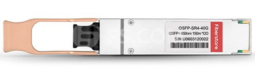
QSFP-40G-SR4 module is one of the most popular fiber optic transceiver for 40G short distances transmission, designed with 40GBase-SR4 standards. It is able to support high-bandwidth 40G signal transmission through 12-fiber parallel fiber, which is always terminated with MPO/MTP multi-fiber connectors. How long can it transmit 40G signals? If it works with OM3, it can support the 40G link at lengths up to 100 meters. If it transmit the 40G signals through OM4, the distance can be longer, 150 meters. In addition, QSFP-40G-SR4 module has the ability to connect four SFP-10G-SR modules by an 8-fiber MTP to 4 duplex LC cable. The following is an example of this module working with OM4 that you can find at FS.COM.
QSFP-40G-CSR4 Module Solution
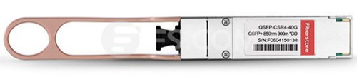
As for QSFP-40G-CSR4 module, it is always referred to as an upgraded version of QSFP-40G-SR4 module that has a better performance to support 40G short distance transmission. Its working principle is similar to the previous one, which also works through 12-fiber parallel cables with MPO/MTP connectors to support 40G optical link. Besides, connection with four 10GBase-SR interfaces still can be done in a parallel 4x10G mode by using duplex fiber breakout cables. What higher performance does QSFP-40G-SR4 module have? In fact, it is reflected on the transmission distance which is extended to 300 meters through OM3 and 400 meters over OM4. Here offers an example of QSFP-40G-CSR4 module that works with OM3 for your reference.
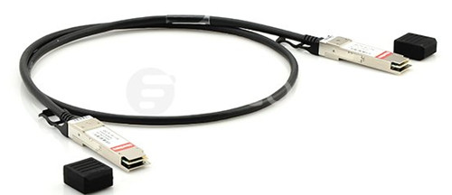
40GBASE-CR4 QSFP+ Direct Attach Cable (DAC) Solution
40GBASE-CR4 QSFP+ DAC can be also called 40GBASE-CR4 QSFP+ cable, which is very different from the first two 40G solutions. It is a pre-terminated copper cable with both ends terminated with QSFP+ modules. As for its working principle, it uses four lanes of twinaxial cable delivering serialized data at a rate of 10.3125 Gbit/s per lane to finish the 40G signal transmission.
Compared to the above-mentioned 40G modules, 40GBASE-CR4 QSFP+ DAC has a much lower manufacturing cost which is always not considered as a real optics, because of no expensive lasers or electronic components. At the same time, the transmission distance is also much shorter limited by the property of copper cable. In fact, it can only support the 40G signal transmission with a reach of 7 meters. Here also lists an example of 40GBASE-CR4 QSFP+ DAC for you to get a better understanding of the differences between this one and the above-mentioned modules.
Conclusion
If the 10G Ethernet network can not meet your demands any more, you are suggested to deploy 40G Ethernet network for much higher bandwidth and faster data transmission rate. As for the 40G solutions for short distance transmission, you can choose it according to the transmission distance your network requires. In general, 40GBASE-CR4 QSFP+ DAC would be a good choice to support your system within 7 meters with the lowest price, while QSFP-40G-SR4 module is much more suitable to be used in the application within 150 meters. As for QSFP-40G-CSR4 module, it is the most expensive but optimal solution that has the ability to support 40G signal transmission at lengths up to 400 meters.
komentiraj (0) * ispiši * #
